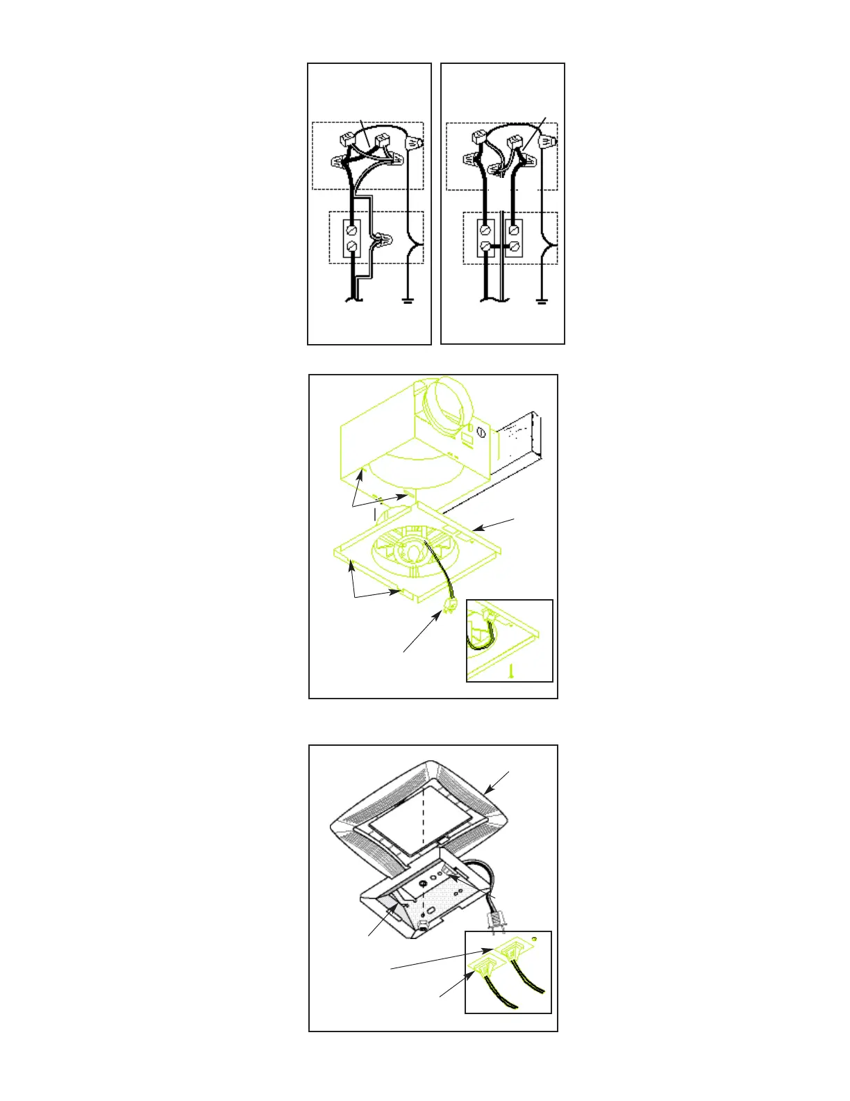
WIRING
Refer to Figures 5 and 6.
All wiring must comply with local codes and unit
must be properly grounded.
1. Run 120vAC house wiring (with ground) from wall
switch to fan location.
2. Insert and secure an approved box connector into
wiring entrance hole.
3. Pull wires through box connector and into junction
box. Tighten box connector.
4. If a single switch will be used to control both the fan
and the light, make wiring connections as shown in
Figure 5.
If a double switch will be used for separate control of
the fan and light, make connections as shown in
Figure 6.
NOTE: If a double switch is used, the wiring
connections determine which receptacle will be used
for the fan motor plug and which receptacle will be
used for the light plug. Make note of this when making
the wiring connections.
5. Connect the green (or bare) ground wire to the green
ground lead.
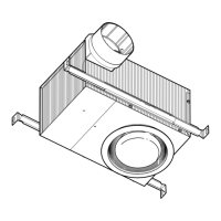
POWER/BLOWER UNIT INSTALLATION
Refer to Figure 7.
1. Place power/blower unit into housing so that mounting
plate's tabs insert into slots in housing.
2. Press other end of mounting plate down until it is
firmly seated over scroll and plug-in receptacles.
3. Secure mounting plate to housing with provided
screw.
4. Insert motor plug into junction box receptacle.
COMPLETING INSTALLATION
Refer to Figure 8.
1. Place reflector into grille.
2. Align grille/reflector assembly with housing and
insert light plug into receptacle in junction box.
3. Remove acorn nut from threaded stud on
mounting plate.
4. Place reflector over stud and secure with acorn
nut.
5. Install lamp NEMA type CFQ13W/G24q (not
provided) into socket.
6. Install lens by squeezing both sides and inserting
lens tabs into slots in grille.
S
INGLE SWITCH CONTROL
CONTROL DE UN SOLO
I
NTERRUPTOR
DOUBLE SWITCH CONTROL
CONTROL DE DOS
INTERRUPTORES
WHITE
B
LANCO
WHITE
BLANCO
BLACK
NEGRO
120vAC
120v AC
GROUND
D
I TIERRA
B
LACK
N
EGRO
BLACK
NEGRO
120vAC
120v AC
GROUND
D
I TIERRA
ALAMBRADO
Vea las figuras 5 y 6
Todo el alambrado debe cumplir con los
códigos locales y las unidades deben estar
conectadas a tierra apropiadamente.
1. Ponga el alambrado de casa de 120v CA
(conectado a tierra) desde el interruptor de
pared hasta la ubicación del ventilador.
2. Inserte y asegure un conectador de caja
aprobado en el agujero de entrada del
alambrado.
3. Jale los alambres por el conectador de caja
y hacia adentro de la caja de registro.
Apriete el conectador de caja.
4. Si solo un interruptor se va a usar para
controlar el ventilador y la luz, haga las
conexiones del alambrado como se muestra
en la figura 5. Si un interruptor doble se va a
usar para el control separado del ventilador
y la luz, haga las conexiones como se
muestra en la figura 6.
NOTA: Si se usa un interruptor doble, las
conexiones de alambrado determinan que
receptor será usado para el enchufe del
motor del ventilador y que receptor será
usado para el enchufe de la luz. Haga nota
de esto cuando está haciendo las
conexiones de alambrado.
5. Conecte el cable verde (o desnudo) de tierra
al conductor a tierra verde.
INSTALACIÓN DE LA UNIDAD DE
PODER/VENTILADOR
Vea la Figura 7.
1. Coloque la unidad de poder/ventilador a la
cubierta de tal forma en que las lengüetas de
las placas de montaje se inserten en las
ranuras de la cubierta.
2. Presione el otro lado de la placa de montaje
hasta que esté firmemente fijado sobre los
módulos de control y de enchufe.
3. Fije la placa de montaje a la cubierta con el
tornillo suministrado.
4. Inserte el enchufe del motor en el receptor
de la caja de registro.
COMPLETANDO LA INSTALACIÓN
Vea la Figura 8.
1. Coloque el reflector en parrilla.
2. Alinee a asamblea de grille/reflector con el
enchufe ligero de la cubierta y del relleno en
receptáculo en caja de ensambladura.
3. Quite la tuerca de la bellota del perno
prisionero roscado en la placa de montaje.
4. Coloque el reflector sobre el perno prisionero
y asegúrelo con la tuerca de la bellota.
5. Instale el tipo CFQ13W/G24q de la nema de
la lámpara (no proporcionado) en el zócalo.
6. Instale la lente exprimiendo ambos lados e
insertando lengüetas de la lente en ranuras
en parrilla.
SLOTS
RANURAS
MOUNTING PLATE
PLACA DE MONTAJE
MOTOR PLUG
ENCHUDE DEL
MOTOR
INSERT TABS
INTO SLOTS
INSERTE LAS
LENGÜETAS EN
RANURAS
GRILLE
PARRILLA
LAMP SOCKET
ENCHUFE DE
LAMPARA
REFLECTOR
REFLECTOR
LIGHT PLUG
ENCHUFE DE LUZ
FAN PLUG
ENCHUFE DEL VENTILADOR
FIGURE 7
FIGURE 8
FIGURE 5
FIGURE 6
BLUE
AZUL
BLUE
AZUL
 Loading...