Floor Inlet Installation in
New & Existing Construction
MODEL CI370 or 360 SERIES INLETS
(361 Rough-in)
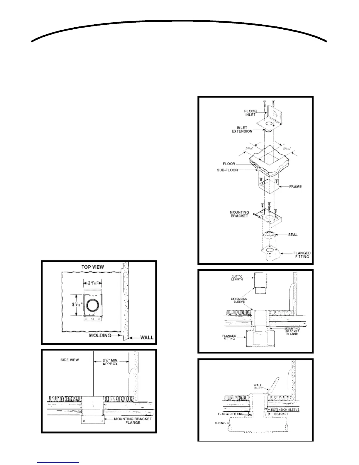
1. Refer to Figures 41 and 42. After floor inlet location
has been selected, cut a 3 1⁄16" x 2 9⁄16" square hole
in floor. Center line of inlet must be located at least 2
1⁄2" from wall to allow cover to be opened when hose
is inserted.
2. Determine direction of tubing and attach appropriate
flanged fitting to mounting bracket with four (4) screws
supplied. Be sure mounting bracket flange does not
interfere with tubing and seal is securely
in place.
3. Refer to Figure 43. Position bracket with frame and
flanged fitting assembly into cutout from below and
secure to sub floor.
4. Refer to Figure 44. Large end of Model 399 extension
sleeve should be cut to length to allow proper seating
of inlet against floor or carpet.
5. Refer to Figure 45. Pull low-voltage 2-conductor wire
through mounting bracket and attach to terminal
screws on back of floor inlet. Cement extension
sleeve to Model CI370 or 360 inlet. Insert extension
sleeve through vinyl gasket in mounting bracket and
firmly seat into flanged fitting.
6. For convenience of operation, floor inlet should be
installed to open back toward wall.
7. Refer to Figure 43. Secure floor inlet in place with two
s c r e w s .
20
FIGURE 41
FIGURE 42
FIGURE 44
FIGURE 45
FIGURE 43
 Loading...