29
GB
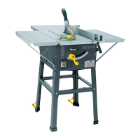
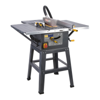
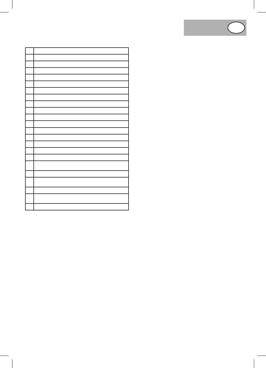
COMPONENTS AND CONTROLS (PIC.1)
FITTING THE RIVING KNIFE. (PIC. 2)
Tofittherivingknife,removethetableinsert.(Pic. 1) 16.With
the table insert removed the two rivingknife securing socket
screws can be seen (Pic. 2). Using asuitablesizedhex key
slacken the two socket screws, locate the riving knife and
securewiththetwosocketscrews.See for the
correctsettingoftherivingknife.
FITTING THE BLADE GUARD. (PIC. 3)
The blade guard (Pic.1)8isattachedtotherivingknife.Remove
the nylok nut and washer from the guard securing coach bolt
and remove the guard securing coach bolt from the blade
guard.Locatethebladeguardovertherivingknife,reinsertthe
guard securing coach bolt and refit the nylok nut and washer
(Pic.3).Checktheoperationofthebladeguardensuringthatit
iscorrectlyfittedandoperatesfreely.
MOUNTING THE ELEVATING HANDLE (PIC. 4)
The elevating screw is located at the front of the machine
and has the locking knob (Pic.1)14.alreadyfitted.locatethe
elevating handle onto the end of the screw and secure by
tightening the securing screw in the handle (Pic. 4).
MOUNTING THE TILTING HANDLE (PIC. 5)
The tilting screw is located at the side of the machine (Pic. 1)13.
Locate the tilting handle onto the end of the screw and secure
by tightening the securing screw in the handle (Pic. 5).
The blade has been set at the factory to be at an angle of
90° to the table.To check the angle elevate the bladeto its
highest position and using an engineers square or a set square
positioned against the table and the blade, check that the angle
isat90°(Pic. 6).Ifadjustmentisrequiredcarefullyturnthetable
sawover andremove thebottom coverplate.Identifythetilt
angle operating screw (Pic. 7).Theoperatingscrew hastwo
setsof adjustmentandlocking nutsfitted.Thesetof nutsat
themotorendofthescrew,areforsettingthebladeat90°to
thetable0°ontheanglescale.Thesetattheotherendofthe
screw,areforsettingthebladeat45°tothetable45°onthe
anglescale.
SETTING THE BLADE AT 90° TO THE TABLE (PICS.
7 TO 9).
Loosen the lock nut (Pic. 8.1) using two wrenches, one for the
lock nut and one for the adjustment nut (Pic. 8.2) on the motor
end of the operating screw (Pic. 7) and turn the adjustment
nut until the blade is at the 90° to the table. Then turn the
lock nut (while holding the adjustment nut in position) to fix
the adjustmentnut in place. Check the position of the angle
indicatorpointer against the angle scale and adjust to 0° by
looseningthecrossheadscrewandsettingthepointeron0°on
the angle scale (Pic. 9).
SETTING THE BLADE AT 45° TO THE TABLE (PICS.
To check the angle, elevate the blade to its highest position and
usingthetilthandletiltthebladeasfaras itwillgo.Usinga
suitable set square, check the angle of the blade to the table
is at 45°(Pic. 10).If adjustmentis required,locatethe set of
adjustment and locking nuts on the tilt angle operating screw
furthest away from the motor (Pic. 7).Loosenthelocknut(Pic.
11.1) using two wrenches, one for the lock nut and one for the
adjustment nut (Pic. 11.2) and turn the adjustment nut until the
bladeisat45°tothetable.Thenturnthelocknut(whileholding
theadjustmentnutinposition)tofixtheadjustmentnutinplace.
Check the position of the angle indicator pointer against the
anglescaleitshouldnowalignwiththe45°mark.
CHECKING THE BLADE ALIGNMENT (PICS. 12 TO
15)
To check that the blade is set parallel to the two mitre gauge
guidegroovesmachinedinthetable(oneoneithersideofthe
blade).Elevatethebladetoitshighestpointandmarkan“X”on
oneoftheteethwhichisset(Bent)totheleftandtothefront
of the blade slot in the table insert (Pic. 12).Positionthehead
of the combination square in the groove and adjust the blade
of the square so that it just contacts the tip of the marked tooth
(Pic. 13).Slidethecombinationsquaretowardstherearofthe
table and rotate the blade so that the marked tooth is to the rear
oftheslotinthetableinsert.Checkthatthemarkedtoothagain
1
Table saw
2
Mitre gauge
3
Ripfence
4
Ripfencemountingblock
5
Ripfencesecuringknobsx2
6
Ripfenceadjustingknob
7
Rivingknife
8
Blade guard
9
Legsx4
10
Uppersupportstrutx4
11
Lowersupportstrutx4
12
Table elevation handle
13
Blade tilting handle
14
Locking knob
15
Table
16
Table insert
17
Tableextension(Left)
18
Table extension support struts
(Left)x2
19
Tableextension(Right)
20
Table extension support struts
(Right)x2
21
Tableextension(Rear)
22
Table extension support struts
(Rear)x2
23
No Volts ON/OFF switch
 Loading...