30
GB
justcontactsthebladeofthecombinationsquare.toseeifthe
marked tooth again contacts the blade of the square (Pic. 14).
If the marked tooth just contacts the combination square blade,
when the marked tooth is positioned at the front and rear of
the blade slot in the table insert the saw blade is parallel to the
mitregaugegroove.Ifthebladeisnotparalleltiltthebladeto
45°carefully turn the table saw over and remove the bottom
coverplate.Loosenthefourbolts(Pic. 15) and adjust the motor
unit until the blade is set parallel to the mitre gauge groove and
thenretightenthescrews.Repeattheaboveprocedureuntilthe
bladeisparalleltothemitregaugegrooves.
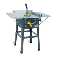
ASSEMBLING THE BASE (PIC. 16)
Account for all parts and lay out ready for assembly. The
wrenchesrequiredforthisassembly,arenotsupplied.Youwill
need assistance with this operation. Examine the exploded
diagram making sure that all parts are in the correct relation to
eachother.Putawasherontothecoachbolt.Takeoneofthe
foursupportlegs.Takethelongupperstrutandaligntheholes
inthesupportlegandinsertthecoachbolt.Placewasheron
the protruding end of the coach bolt and tighten the hexagonal
nutfingertight.Taketheshortupperstrutandrepeatoperation
regardingsecuring withthe hexagonal nuts andcoach bolts.
Repeat the operation until all four support legs have been
securedtotheuppersupportstruts.Locatethelonglowerstruts
and the short lower struts and secure in the same operation as
theupperstruts.Onceallnutsarefingertight,tightenALLnuts
toasuitabletorque.
MOUNTING THE TABLE SAW TO THE BASE (PIC.
17)
With an assistant lift the table saw onto the base. Care is
required as the machine is not secured at this stage and is liable
toslipoffthebasepossiblycausinginjury.Putthefourwashers
ontothefourhexagonalbolts.Whileonepersonsecurelyholds
the table saw in place locate the bolt though the table saw base
(Pic. 17)passingthroughtheholeinthebase.Takethewasher
andhexagonalnut,securefingertight.Repeatthisoperationon
allfourcorners.UsingsuitableringspannerstightenALLfour
nuts.
MOUNTING THE RIP FENCE (PIC. 18 TO 20)
Locate the rip fence mounting block (Pic. 1) 4onto theslide
profile located along the front edge of the table saw, ensuring
that the clamping plate is located inside the groove in the slide
profile (Pic. 18).Positionthemountingblocktotherightofthe
bladeandsecureusingthelockingknob(Pic.18).Usingthetwo
coach bolts and knobs secure the rip fence onto the mounting
block (Pic. 19).Theripfencecannowbeadjustedfromleftto
rightandfromthefronttoback.(Pic. 20)
FITTING THE MITRE GAUGE (PIC. 21)
The mitre gauge simply locates in the location grooves one on
either side of the blade (Pic. 21).andcanbeusedforcuttingat
variousangles.
MITRE GAUGE ADJUSTMENT (PIC. 21)
To check the accuracy of the mitre gauge, ensure that the
pointerissetto0°ontheanglescaleandperformacut.Check
theangleofthecut,ifitisnotat90°adjustthemitregaugeuntil
a90°cutisachieved.Checkthepositionofthepointeragainst
the angle scale and if required adjust the position of the pointer
to0°byslackeningthecrossheadpointersecuringscrewand
setthepointertozeroontheanglescaleandre-securewiththe
crossheadscrew.
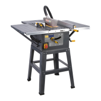
FITTING THE TABLE EXTENSIONS (PIC. 22)
This table saw is supplied with left, right and rear table extensions
tosupportlargerpiecesofmaterial.Theseextensionscanbe
fittedindividuallyorinanycombination.Inordertofitthetable
extensions the table saw must be removed from the support
legs and the bottom cover plate removed. The left and right
table extensions are the same size and can be fitted to either
sideofthetablesaw.Securethetableextensiontothetable
saw using the bolts provided (Pic. 23).Usingtwo ofthefour
short support struts and attach one end to the outer edge of the
extension and the other to the table saw (Pic. 24).Repeatthis
procedurefortheremainingtableextensions.NoteThesupport
strutsforthereartableextensionarelonger.Whenthetable
extensions are fitted as required check them for level using a
spiritlevelandadjustasrequired.(Pic. 25)
NO VOLTS ON/OFF SWITCH
Thismachineisfittedwitha“NoVoltsSwitch”.Intheeventof
a mains power failure or if the mains plug is removed from the
mainssupplysocketbefore themachineis switchedoff.The
machinewillnotre-startwithoutwarningwhenthemainssupply
is restored or the mains plug is re-connected to the mains
supply, until the machine is switched ON at the ON/OFF switch
fittedtothemachine.
WARNING!
Before switching the table saw ON, make sure the blade guard is
correctlyinstalledandoperatingproperly.Checkthattheblade
issetto90°andatitslowestposition.Ensurethatthetableis
clearofanytoolsorothermaterials.Ensurethatallnuts,bolts
andotherfasteningsaresecure.Startingandstopping(Pic. 26)
Tostartthemachine,pushthe“ON”switch(Pic. 26).Tostopthe
machine,pushthe“OFF”switch(Pic. 26).Ifthemachinemakes
any unusual noise or vibrates excessively, STOP the machine
immediatelyandinvestigatethecauseandrectify.Ifthecause
cannot be identified NO NOT use the machine and contact your
nearestservicecentre.
CONTROLS AND ACCESSORIES.
The following is a brief description of each control and accessory
anditstypicaluses.
THE ELEVATING HANDLE. (PIC. 27)
Theelevatinghandleisusedtoraiseandlowertheblade.Turn
the handle clockwise to lower the blade
andcounterclockwisetoraisetheblade.
THE TILTING HANDLE. (PIC. 28)
 Loading...