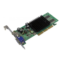
MS-8816/8817/8818 nVIDIA GeForce2 MX
TM
Graphics Processing Unit
User’s Guide
1-8
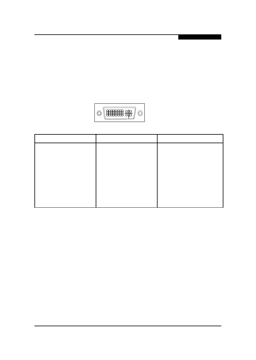
7. DVI Connector
The mechanical interconnect includes 29 signals contacts, which are
divided into two sections. The first section is organized as three
rows of eight contacts. The second section contains five signals that
are designed specifically for analog implementations.
18
9
16
17
24
C1 C2
C3
C4
C5
Pin Signal Pin Signal Pin Signal
1 T.M.D.S. Data 2- 9 T.M.D.S. Data 1- 17 T.M.D.S. Data 0-
2 T.M.D.S. Data 2+ 10 T.M.D.S. Data 1+ 18 T.M.D.S. Data 0+
3 T.M.D.S. Data 2/4 Shield 11 T.M.D.S. Data 1/3 Shield 19 T.M.D.S. Data 0/5 Shield
4 T.M.D.S. Data 4- 12 T.M.D.S. Data 3- 20 T.M.D.S. Data 5-
5 T.M.D.S. Data 4+ 13 T.M.D.S. Data 3+ 21 T.M.D.S. Data 5+
6 DDC Clock 14 +5V Power 22 T.M.D.S. Data Clock Shield
7 DDC Data 15 Ground 23 T.M.D.S. Clock+
8 Analog Vertical Sync 16 Hot Plug Detect 24 T.M.D.S. Clock-
C1 Analog Red C2 Analog Green C3 Analog Blue
C4 Analog Horizontal Sync C5 Analog Ground