LOW LEVELH I LEVEL
GNDGNDL- R- L- R-
L+ R+ L+ R+ GNDGND
+12V +12V
+12V +12VREM
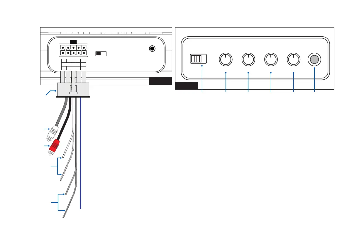
PANEL CONNECTIONS AND FEATURES
3
R- R-L- L- NC
R+ R+L+ L+ REM
REM DC
REMOTE
VOLUME
LINE IN H I-LEVEL
G. Input Gain Control
After you have installed your system, turn this GAIN control to minimum (counter-clockwise).
Turn the head unit on and adjust the head unit volume to a comfortable listening level.
Slowly turn up the subwoofer input gain control until you hear a small amount of distortion.
Then reduce the level until the distortion is completely gone. Leave the control at this setting.
H. Bass Boost
The BASS BOOST feature will increase the sound level in the bass frequencies.
I. Low Pass Filter (LPF)
This control permits you to dene the frequency range you want the subwoofer amplier to
receive. The subwoofer will reproduce all sound BELOW the frequency you set.
Note: The low pass lter frequency can be higher or lower than the marked
Frequency by as much as +/- 20% tolerance.
J. Phase Switch
Use this switch to help compensate for time alignment problems in the system. Such
problems usually result from having the subwoofer at a dierent distance from the listener
than the other speakers in the system.
FIGURE 1
FIGURE 2
PHASE
LEVEL
SUB
SONIC
BASS
BOOST
LOW
BASS
PWR
PRT
180° 0°
MIN MAX 10HZ 50HZ 50HZ 180HZ0dB 12dB
12v remote
input
G H I J K L
RCA/Low Level Input
(white - left)
RCA/Low Level Input
(red - right)
Speaker/High Level Input
(left white + white/black)
Speaker/High Level Input
(right grey + grey/black)