Do you have a question about the O.S. engine FS-70S and is the answer not in the manual?
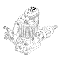
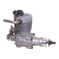
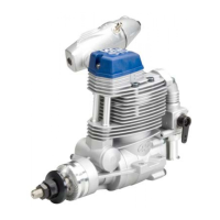
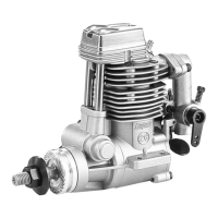
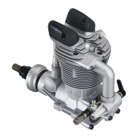
Guidelines for mounting the engine securely in the airframe and ensuring accessibility.
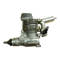
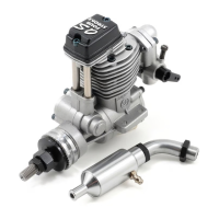
Steps to correctly screw and secure the exhaust header pipe and silencer.
Instructions for reversing the carburettor for optimal positioning and choke lever.
How to adjust the choke valve lever and rod for operation, ensuring secure mounting.
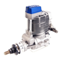
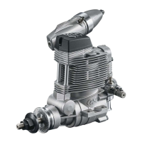
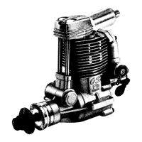
Technical details like displacement, bore, stroke, output, and weight.
Recommended fuel tank size and placement relative to the engine's center line.
Details on recommended fuel types, nitro content, and lubricant levels for performance.
Information on the recommended O.S. Type "F" glowplug for four-stroke engines.
Guidance on selecting and mounting the correct propeller for the engine.
Step-by-step instructions for both electric and hand starting the engine safely.
Procedure for the initial break-in period to ensure engine longevity and performance.
How to adjust needle-valve, mixture control, and throttle stop screws for optimal performance.
Resets the mixture control valve to its factory specified position for correct adjustment.
Importance of keeping carburettor orifices clean for reliable engine performance.
Procedure to check and adjust valve clearances when the engine is cold.
How to fit an extension for external adjustment of the needle valve.
General advice on engine care, cleaning, and long-term storage to prevent damage.
A comprehensive list of available spare parts with their corresponding code numbers.
| Brand | O.S. engine |
|---|---|
| Model | FS-70S |
| Category | Engine |
| Language | English |