
F
Frank MillsAug 8, 2025
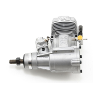
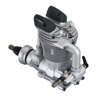
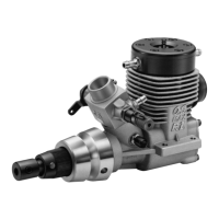
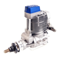
What to do if O.S. Engine fires intermittently but does not run?
- WwericksonAug 8, 2025
If your O.S. Engine fires intermittently but doesn't run, it could be due to several reasons. First, make sure you have enough fuel in the tank by filling it up. A deteriorated glowplug can also cause this issue, so consider replacing it. Check for a clogged fuel filter or a dirty silencer; clean or replace the fuel filter and clean inside the silencer. If the engine has overheated, allow it to cool down. Ensure you're not disconnecting the plug battery too soon; wait until the RPM becomes stable. Finally, check for air bubbles in the fuel and fit O rings to the tank screws to prevent them.