4
1310836-07 | MAR 02 2016
WIRE GAUGE FOR 3% VOLTAGE DROP IN SUPPLY CIRCUITS
Amps 20 30 40 50 60 70 80 90 100 120 140 160
2 14 14 14 14 14 14 14 14 14 14 14 14
3 14 14 14 14 14 14 14 14 14 14 14 14
4 14 14 14 14 14 14 14 14 14 14 14 12
5 14 14 14 14 14 14 14 14 14 12 10 10
5 14 14 14 14 14 14 14 14 12 10 10 10
7 14 14 14 14 14 12 12 12 10 10 10 8
8 14 14 14 14 12 12 12 10 10 10 8 8
9 14 14 14 12 12 12 10 10 10 8 8 8
10 14 14 14 12 12 12 10 10 10 8 8 8
12 14 14 12 12 10 10 10 8 8 8 8 6
14 14 14 12 10 10 10 8 8 8 6 6 6
16 14 14 12 10 10 8 8 8 8 6 6 6
18 14 12 10 10 8 8 8 8 8 8 8 5
20 14 12 10 10 8 8 8 6 6 6 5 5
25 12 10 10 8 8 6 6 6 6 5 4 4
30 12 10 8 8 6 6 6 6 5 4 4 3
35 10 10 8 6 6 6 5 5 4 4 3 2
40 10 8 8 6 6 5 5 4 4 3 2 2
45 10 8 6 6 6 5 4 4 3 3 2 1
50 10 8 6 6 5 4 4 3 3 2 1 1
INSTALLATION
INSTALLATION REQUIREMENTS
1
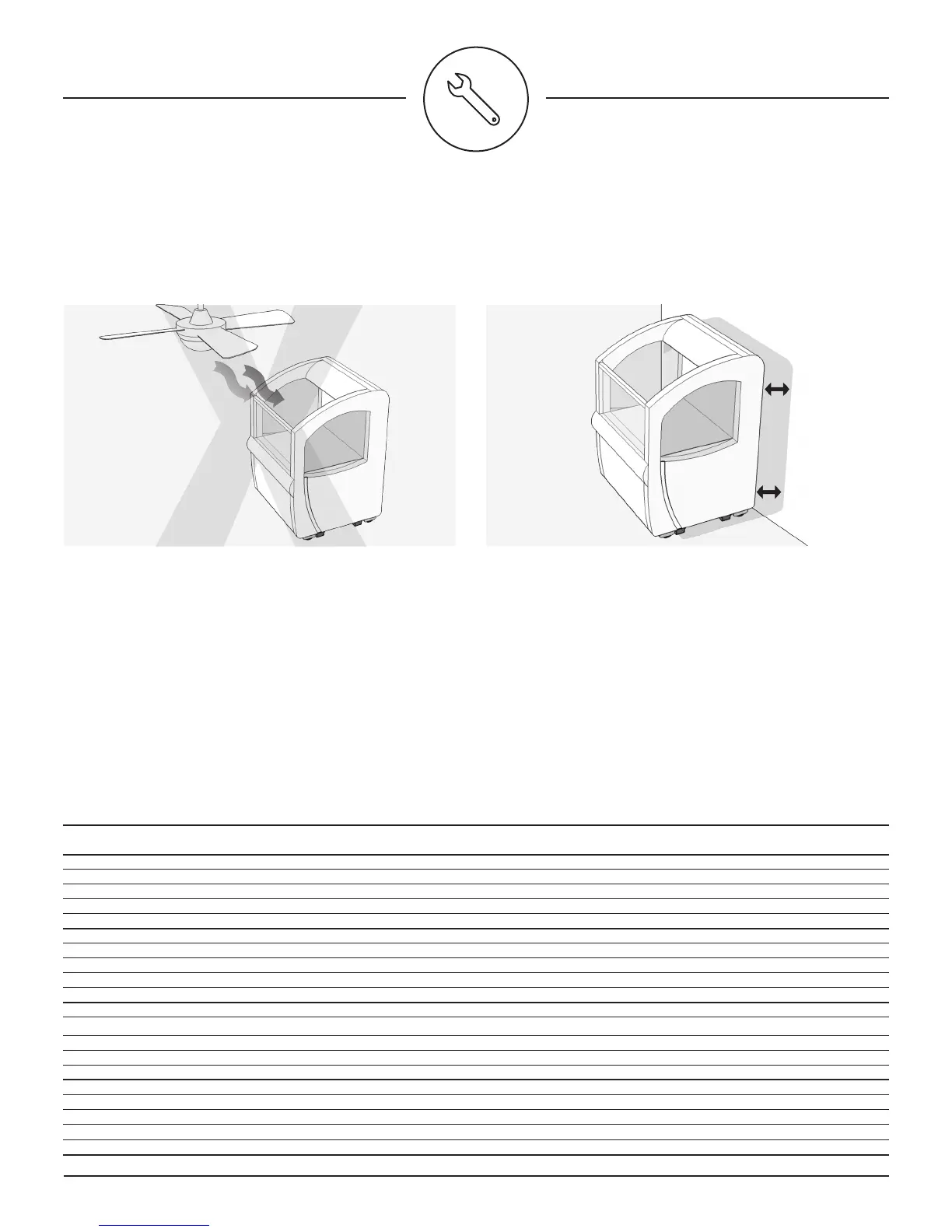
DO NOT place the cooler in a location with air dras that
could disrupt the air curtain
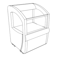
2
There must be at least 2 inches of space behind the unit
at all times to ensure proper air ow.
ELECTRICAL REQUIREMENTS
• A dedicated power line from the breaker box
• 20 Amp Breaker
• The wire gauge should be suicient to limit voltage
drop under 15 amp load to 3%.
Please consult factory for voltage drop calculations based
on line lengths, see below.
Installation
3
DO NOT place the cooler in a location with ambient
temperatures over 75°F or 50%RH
4
Cooler should not be placed near other equipment that
can be expelling heat. (example, Chicken warming stations)
Note: Even though
there are no vents
at the back of
the Oasis, the air
intake will come
from behind the
unit.