2
6
2.1
2.2
80 cm. 70 cm.
0÷15 4x6 - - -
0÷30 6x10 - 1/4"-
0÷125 -
DN 10
3/8" Ø16
0÷155 -
DN 15
1/2" Ø20
1/2" ANSI
0÷260 -
DN 20
3/4" Ø25
3/4" ANSI
0÷420 -
DN 25
1" Ø32
1" ANSI
➜
➜
2
Fig. 7/A
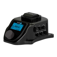
Fig. 6
RIGHTWRONG
FILTER FOOT VALVE
Right
Right
Right
Pipe size according
with table C
Wrong
Risk of clogging of pump valves
Wrong
In the highest point of the piping
the fluid vein breaks
Wrong
Pipe size not according
with table C
• A proper installation and sizing of the suction line are of particular importance for a correct operation of the pump, the following
factors shall be taken into account
:
A) Pipe inner diameter
The pipe internal diameter will be chosen according to the pump flow rate (see table C)
.
The pump connections are oversized, in order to cover all applications.
B) Length of the piping
Suction piping is to be as short as possible, following the indications of table C
it is suggested:
- Max suction lift 1,5 metres
- Total length 2,5 metres (upright plus horizontal)
C) Arrangement of the suction line
For the arrangement of the suction line see Fig. 7/A and 7/B.
Table C
Relationship between flow rate and pipe size
FLOW RATE L/h
PIPE WITH
FITTINGS
FLANGED
PIPE
THREADED
PIPE
PVC GLUED
PIPE
SUCTION LINE
ADJUSTMENT SIDE
HYDRAULIC SIDE
ASSEMBLING AREA
• Provide with adequate clearance areas and safe access for operation and mainte-
nance, in particular in front of the hydraulic side and of the adjustment knob (fig. 6).
• If the pump is installed outdoors, a shelter is recommend, specially when the pump is
equipped with electric actuators or other delicate devices.
• PP pump heads can work properly only at ambient temperature and metered liquid
temperatures below 40°C.
• If necessary, provide suitable protection from sun rays and check the temperature of
the metered liquid.
INSTRUCTIONS FOR A PROPER INSTALLATION
INSTALLATION
INSTALLATION
 Loading...