X9 Series metering pumps Operating manual
Page 30 Copyright © - OBL Metering pumps - All rights reserved File: UT-4336 – Rev.0
GB
Pumphead disassembling operations for diaphragm replacement are the same for all types of pumps.
We suggest, however, reference to the following figures during operation:
- Pump types LY, LYH: See figure 15 - Pump type LK: See figure 16 - Pump types LN, LP: See figure 17
Proceed as follows:
- release the pump from suction and discharge pipeline, and clean adequately
- dismantle both valve units from the pumphead, then the diaphragm rupture detector
ATTENTION DANGER ! PROTECT PROPERLY FROM EJECTIONS OF PRODUCT UNDER PRESSURE !
- unscrew all locking nuts (pos.100) and remove the pumphead body (pos.21) and the whole sandwich diaphragm (pos.48)
- clean and check the conditions of the inside of the oil chamber (pos.33) and of the replenishing disk (pos.38) which must be
whole and free to move
- assemble the new diaphragm (pos.48) (see figure 14), taking SPECIAL ATTENTION to position the sandwich diaphragm ring
with the hole toward the pumphead and to correctly insert the oil side diaphragm in the relative groove
- verify the free movement of the rupture detector shutter (pos.98), introducing compressed air in the related hole in the
pumphead (see figure 14-D)
- clean and reassemble the pumphead (pos.21) following the instructions in reverse order and figures relative the type of pump
- fasten the pumphead with locking nuts (pos.100), see "Pumphead tightening torque"
- reassemble the diaphragm rupture detector on the pumphead, see "Diaphragm rupture detector resetting"
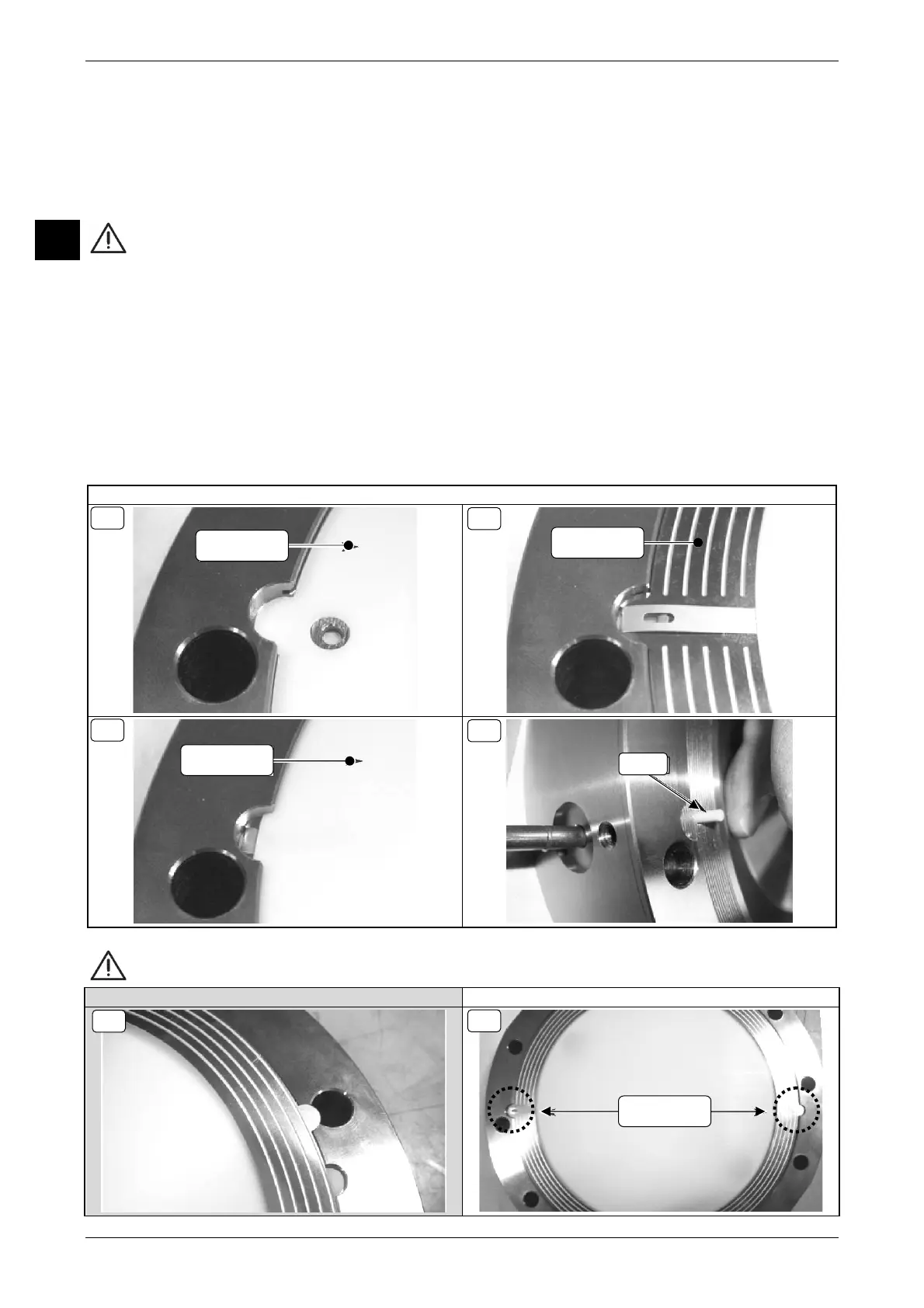
Figure 14 NEW HYDRAULIC DIAPHRAGM ASSEMBLING
In order, first insert the product side holed diaphragm (14-A), then the metallic ring (14-B), then the oil side diaphragm (14-C).
ATTENTION: Correct assembly of the diaphragms and metallic ring is guided by the sides on the pumphead
INCORRECT INSTALLATION CORRECT INSTALLATION
14-A
PRODUCT SIDE
DIAPHRAGM
METALLIC
RING
14-B
14-C
OIL SIDE
DIAPHRAGM
14-D
POS. 98
SIDES
14-F
14-E
 Loading...