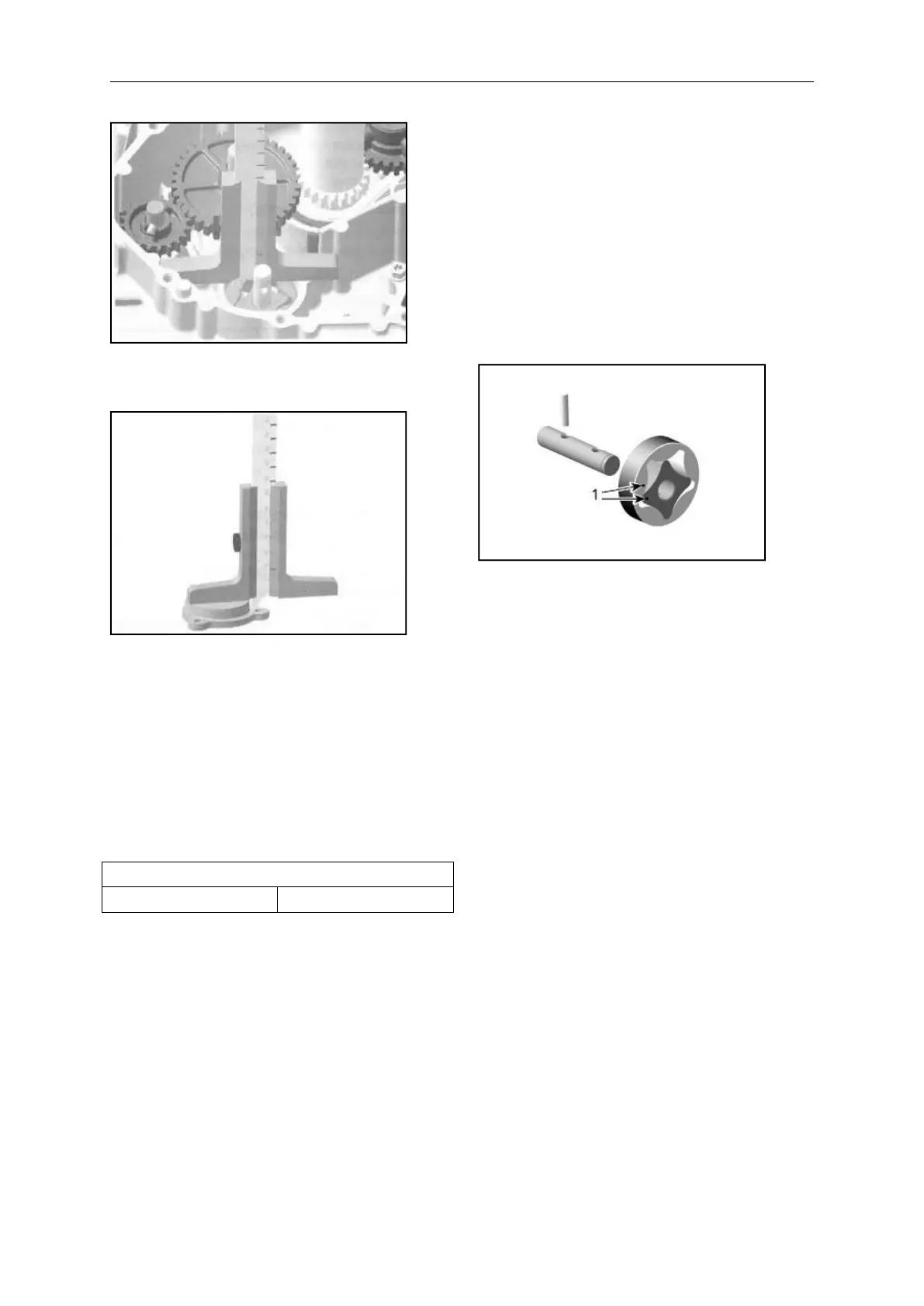
OIL PUMP- MEASUREMENT "A″
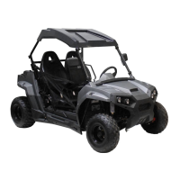
OIL PUMP COVER- MEASUREMENT "B ″
Substract measurement ''B" from
measurement "A" to obtain axial
clearance.
NOTE: When the axial clearance of the oil
pump shaft assembly increases, the oil
pressure decreases.
Installating the Oil Pump
For installation, reverse the removal
procedure.
Pay attention to the following details.
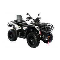
NOTE: When installing the oil pump
rotors, make sure both markings are on
the outer side.
1. Markings
After reinstallation of the remaining parts,
check for smooth operation of the oil
pump assembly.
Testing the Oil Pump Function
After engine is completely reassembled,
start engine and make sure oil pressure is
within specifications (refer to ENGINE OIL
PRESSIRE in this subsection).