8.ENGINE
8-56
NOTE: Make sure the cylinder bore
gauge indicator is set exactly at the
same position as with the micrometer,
otherwise the reading will be false.
Connecting Rod/Piston Pin Clearance
Using synthetic abrasive woven, clean
piston pin from deposits .
Inspect piston pin for scoring,
cracking or other damages.
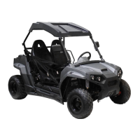
Measure piston pin . See the
following illustration for the proper
measurement positions.
A. Piston pin diameter
Replace piston pin if diameter is out
of specifications.
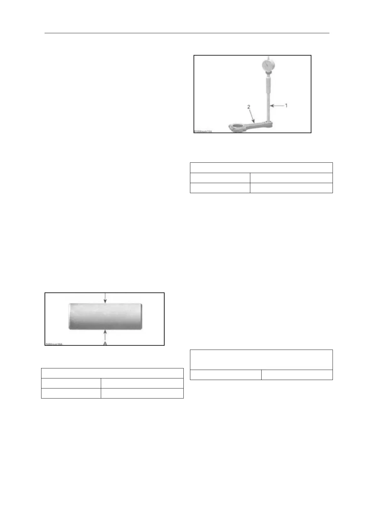
Measure inside diameter of
connecting rod small end bushing .
1. Bore gauge
2. Connecting rod
CONNECTING ROD SMALL END DIAMETER
Replace connecting rod if diameter of
connecting rod sma1l end is out of
specifications. Refer to BOTTOM
END subsection for removal
procedure. Compare measurements to
obtain the connecting rod/piston pin
clearance.
CONNECTING ROD/
PISTON PIN CLEARANCE
Installating the Piston
For installation, reverse the removal
procedure. Pay attention to the
following details.