Apply engine oi1 on the piston pin.
1nsert piston pin into piston and
connecting rod.
For each cylinder, Install piston with
the punched arrow on piston dome is
pointing toward the rear side of the
engine.
Front cylinder: Mark on top of piston must show
to intake side.
Rear cylinder: Mark on top of piston must show
to exhaust side.
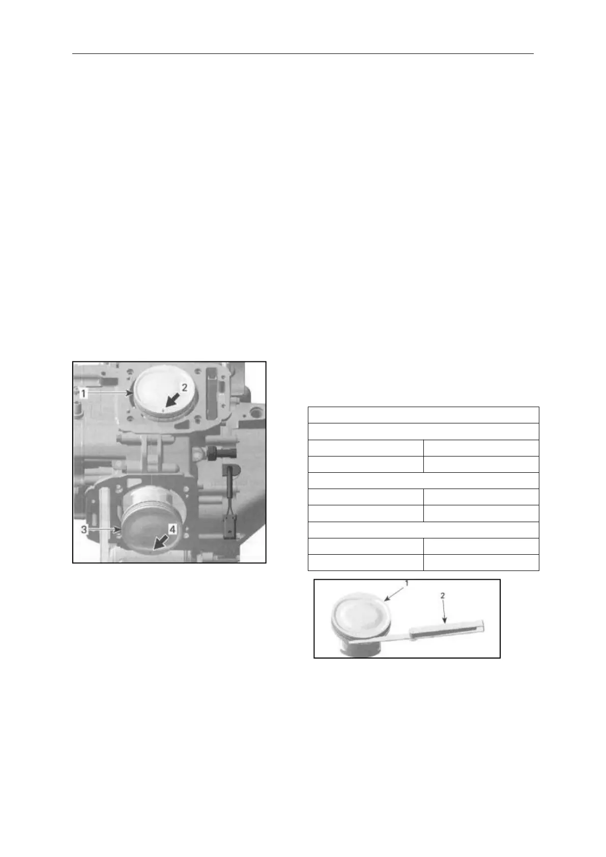
1. Piston of cylinder 1
2. Mark on piston must show to intake
side of cylinder 1
3. Piston of cylinder 2
4. Mark on piston must show to
exhaust side of cylinder 2
PISTON RINGS
Removing the Ring
Remove the piston (see PISTON in
this subsection).
Inspecting the Ring
Ring/Piston Groove Clearance
Using a feeler gauge measure each
ring/piston groove clearance . If the
clearance is too large, the piston and
the piston rings should be replaced.