in crankcase half PT0 side must be
positioned near to oil bore in
counterclockwise direction.
1. Partition
2. Oil bore
3. Crankcase half PTO (inside)
Assembing the Crankcase
The assembly of crankcase is essentially the
re- verse of removal procedure. However,
pay attention to the following details.
Install a NEW crankcase gasket.
Oil the plain bearings before mounting the
crank- shaft.
NOTICE Correctly reinstall crankshaft (refer
to CRANKSHAFT)
Properly reinstall engine oil strainer and
screws. Refer to LIBRICATION SYSTEM
subsection.
Reinstall water pump intermediate shaft
and gears. Refer to WATER PUMP GEARS
in the COOLING SYSTEM subsection.
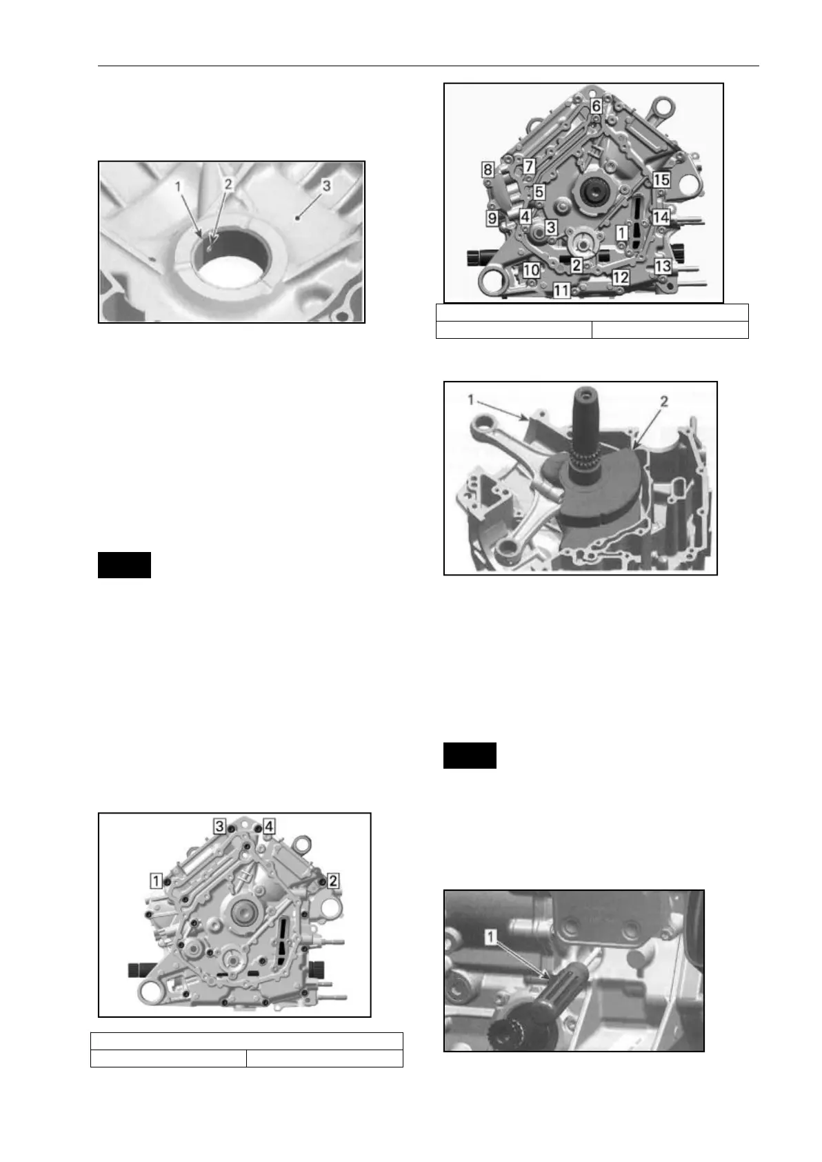
Tightening sequence for screws on
crankcase is as per following illustration.
M8 SCREWS TIGHTENCE SEQUENCE
CRANK SHAFT
1. Crankcase MAG
2. Crankshaft
Crankshaft Locking Procedure
NOTE: When crankshaft is locked, the rear
piston no. 2 is at TDC. Crankshaft can not
be locked at piston no.1 TDC.
NOTICE To see if the rear piston no. 2 is at
TDC ignition refer to CRANKSHAFT TIMING
GEAR in the TIMING CHAIN subsection.
Use a screwdriver to check if the groove in
the crankshaft is aligned with the hole.
1. Screw driver
Lock crankshaft