8.ENGINE
8-87
- Do not apply any thread locker.
- The running direction of the big end
bearings and of the piston pins must not
chan9e.
- Always perform each step on both
connecting rod -Failure to strictly follow
procedure may cause connecting rod
screws to loosen and lead to Severe
engine damage.
NOTICE Connecting rods are asymmetric.
There must be no gap between the small
ends when they face each other.
1. Connecting rod small ends
2. Connecting rod offset
3. Connecting rod screws
CONNECTING RODS SCREWS TIGHTENING
SEQUENCE
Tighten to1/2 of specified torque
Torque by an additional 90±5° turn using
an angle torque wrench
Crankshaft Installating
For installation of crankshaft in
crankcase reverse the removal procedure.
Pay attention to the fol_ lowing details.
Do not mix up the connecting rods of
cylinders1 and2 during installation.
NOTICE Observe the correct installation
position when fitting the crankshaft with
the connecting rods. The connecting
rod MAG side has to face cylinder no. 1.
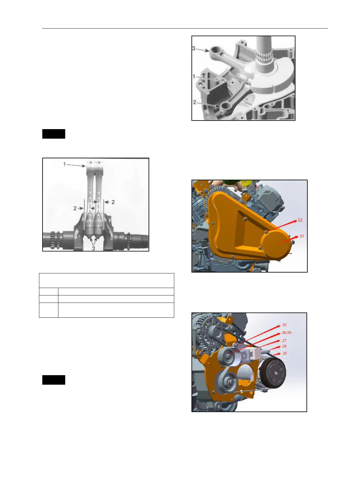
1. Crankcase half MAG side
2. Connecting rod cylinder 1
3. Connecting rod cylinder 2
Air conditioning accessory
maintenance
1.Remove the belt cover
31-belt cover
32-M6 bolt×5
2.Remove the idler gear
3.Remove the elastic belt
25.Elastic belt
26-27.Elastic belt disassembly and assembly tooling
28.Idler
29.M10 nut
30.M8 bolt×3