When rear piston is at TDC ignition, marks on
magneto flywheel “2”and on the magneto
cover are aligned.
1. Mark “2” on magneto flywheel
2. Notch on magneto cover
3. Crankshaft position sensor location
At TDC ignition, the printed marks on the
camshaft timing gear have to be parallel to
cylinder head base. If not, use Allen key to
turn crankshaft 360°
1. Printed marks on camshaft timing gear
2. Cylinder head base
Insert the feeler gauge between the valve
stem end and adjusting screw on the rocker
arm to check the clearance.
If the valve clearance is out of specification,
adjust valves as follows.
Use mean valve of exhaust/intake to
ensure a proper valve adjustment.
Hold the adjustment screw at the proper
position and torque the locking nut.
Repeat the procedure for each valve.
1. Adjustment screw
2. Adjustment nut
3. Feeler gauge
CAUTION: Securely tighten the lock nut
after completing adjustment.
Valve clearance adjuster lock nut:12N.m
Valve clearance of cylinder 1
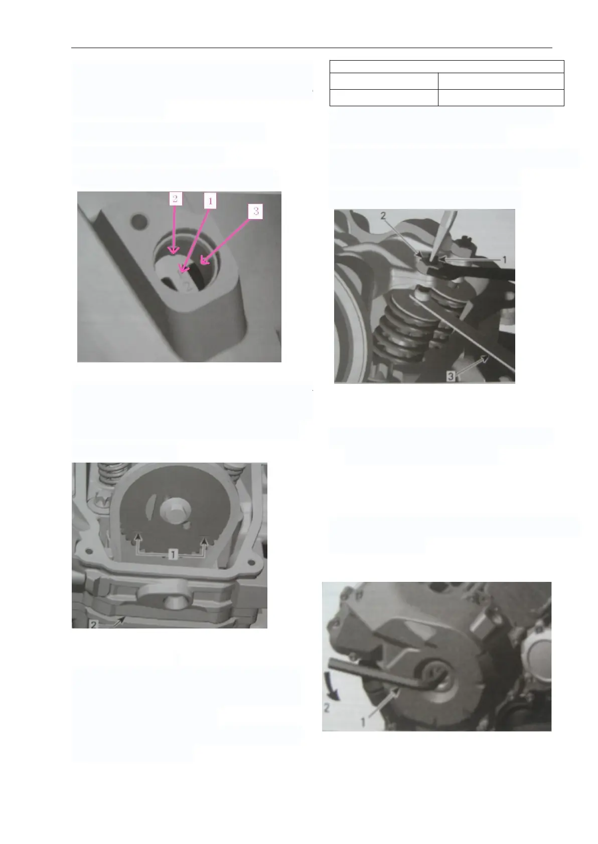
Using a 14 mm Allen key, turn crankshaft 280
°counterclockwise.
1. Allen key 14mm
2. Turn crankshaft 280°counterclockwise