2.PERIODICMAINTENANCE
2-20
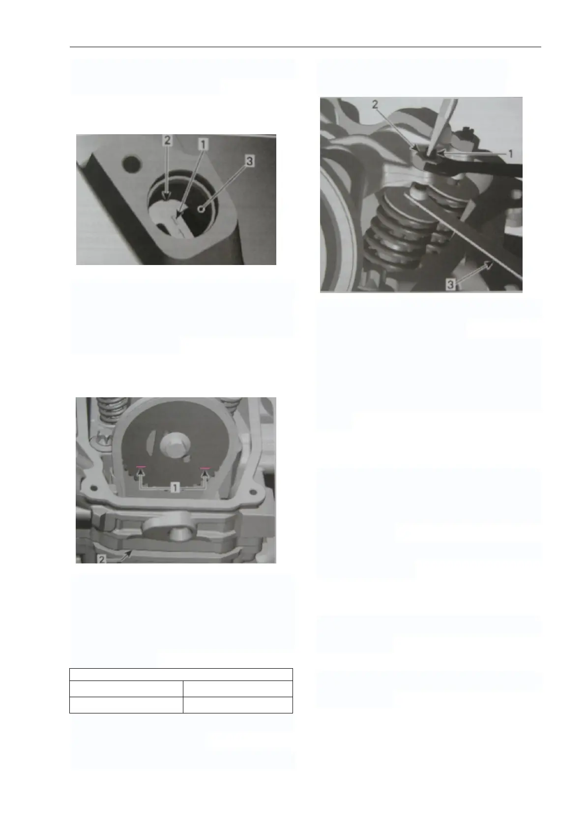
Until marks on magneto flywheel “1” and
magneto cover are aligned.
1. Mark “1” on magneto flywheel
2. Notch on magneto cover
3. Location of crankshaft position sensor
At TDC ignition, the printed marks on the
camshaft timing gear have to be parallel to
timing gear have to be parallel to per
following illustration.
TYPICAL
1. Printed marks on camshaft timing gear
2. Cylinder head base
Insert the feeler gauge between the valve
stem end and adjusting screw on the rocker
arm to check the clearance. If the valve
clearance is out of specification, adjust
valves as follows.
Use mean valve of exhaust/intake to ensure
a proper valve adjustment.
Hold the adjustment screw at the proper
position and torque the locking nut.
Repeat the procedure for each valve.
CAUTION: Securely tighten the locknut
after completing adjustment.
Install the valve cover of both cylinders,
spark plug cable and spark plug of both
cylinders, the plug screw and O-ring of
magneto cover and the crankshaft position
sensor.
SPARK PLUG
In case of serious wear or burn to electrode
or burn to insulator by spark plug or
damage to thread etc, please replace it with
new spark plug
In case of carbon deposit, please use proper
tools for cleaning.
Spark plug gap
Use clearance gauge to measure clearance
of spark plug.
In case of exceeding designated range, then
adjust the gap.