Blower Motor resistor
The blower motor resistor provides
electrical resistance in series to the blower
motor. The fan speed control switch sends
current to one blower resistor pin based on
selected fan speed.
Adding resistance to the circuit slows the
blower motor. Removing resistance from
the circuit speeds the blower motor.
Testing the Blower Motor Resistor
The blower motor resistor cannot be tested
independently from the blower motor.
1.Turn the fan on to low, medium1,
medium2,then high.
2.Read the voltage at the blower assembly
connector for each speed.
If battery voltage is available at each pin of
the blower assembly connector and the
blower motor does not come on. Ensure
there is a good ground. If all electrical tests
are OK. Replace the blower assembly.
Blower speed switch
The blower speed switch sends current to
one pin of the blower motor resistor
d e p e n d i n g o n s e l e c t e d s p e e d .
The blower speed switch also supply power
to AC switch, so AC switch can control AC
system.
Testing the Blower Speed Switch
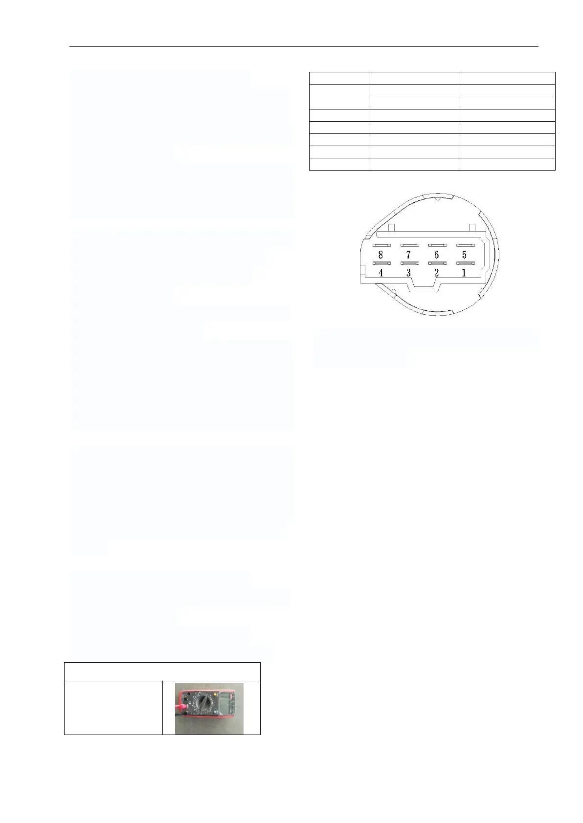
1. Disconnect blower speed switch.
2. Ensure battery voltage is available at pin
1 and 5 (switch side).
3. Disconnect blower speed switch.
4. Test resistance as per following table.