6.ELECTRICAL SYSTEM
6-11
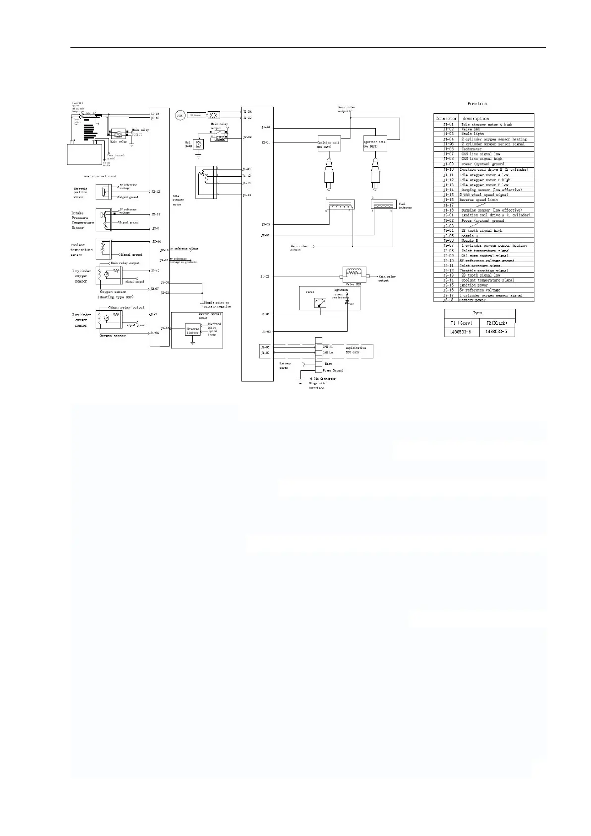
schematic diagram of EFI system
The function of EFI system includes two parts: fuel injection management and ignition
management, which are realized by the following institutions.
(1). ECU: it is responsible for the receiving of sensor signal, the formulation of control
strategy, and the issue of control signal.
(2). Oil supply device: it is composed of oil pump, tubing and injector. The pump pressurizes
the fuel to 250 KPA. The injector is installed on the engine inlet to control the injection
timing and fuel injection amount.
(3). Ignition device: it is composed of ignition module, high voltage wire and spark plug. The
ignition module has a DC capacitor igniter and a high voltage ignition coil, which can raise
the voltage of the battery from 12V to more than 15000V, which also can be transported to
the spark plug by high-voltage wire to generate spark discharge.
(4). Sensors: including: a. The oxygen sensor, which mounted on an exhaust pipe to detect
oxygen concentration in exhaust gases, can realize the closed-loop regulation of the
mixture concentration, and when the closed-loop adjustment, the output of 0 ~ 0.9V
alternating signal can be achieved; b. cylinder temperature sensor, which is installed on the
engine cylinder head to detect the engine body temperature, will affect the starting
thickening amount; c. Crankshaft position sensor, which is integrated on magneto to
provide crankshaft angle signal, is the time reference for fuel injection and ignition control;
d. The throttle position sensor is mounted on the throttle body to measure the rotation