EasyManua.ls Logo

Odyssey I Series - User Manual

Odyssey I Series
3 pages
Print Icon
To Next Page IconTo Next Page
Loading...
MAN# 650045
Series I
ODY-05 VOLTMETER rev. C
Wiring:
GND - Connect to a main ground location.
PWR - Connect to fused switched 12VDC power. (An accessory terminal will work for this.)
DIM - Night Dimming: connect to the head light switch.
SND - Voltage measuring point, usually jumper over to the PWR terminal.
Mounting:
The Series I gauge requires a rectangular hole 2-9/16“ x 1-11/16“. . It should be inserted into the opening
from the front and the U-clamp will be installed from the back. Tighten the two nuts on the U-clamp so that the
gauge is secure. Gauge depth to the back of the case is 1”. Gauge depth including the mounting studs is 1-7/8”.
Factory settings:
Lo warning point: 11.1VDC
Hi warning point: 15.4VDC
The voltage gauge will operate in the voltage range of 8.0 17.0VDC and read correct between the voltage
range of 1.0 - 18.0VDC volts.
It has a user adjustable lower and upper warning level, which can be set to indicate low voltage and
overcharging conditions.
The SND terminal is the voltage sensing input. To read the vehicle system voltage, connect this to the PWR
terminal. To read the voltage at a second battery or other remote location, connect a wire from the SND terminal to
the voltage to be monitored.
Question and Answer IconNeed help?

Do you have a question about the Odyssey I Series and is the answer not in the manual?

Summary

Wiring Connections

GND Terminal

Connect to a main ground location.

PWR Terminal

Connect to fused switched 12VDC power.

DIM Terminal

Connect to the head light switch for night dimming.

SND Terminal

Voltage measuring point, typically jumpered to PWR.

Mounting Instructions

Setting Warning Limits

Enter Set Mode

Turn key on with SND wire not powered to display "SEt".

Set High Warning Point

Power SND to advance to "HI", release to set value.

Set Low Warning Point

Release SND to advance to "LO", release to set value.

Troubleshooting Guide

Gauge Will Not Light Up

Check PWR connection and GND terminal for power and ground.

Service and Repair

Overview

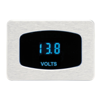
The Dakota Digital Odyssey Series I ODY-05 Voltmeter (rev. C) is a device designed to measure and display vehicle system voltage, with features for user-defined warning limits and easy installation.

Function Description

The primary function of the ODY-05 Voltmeter is to provide a clear, digital display of the vehicle's electrical system voltage. It is capable of operating within a voltage range of 8.0 to 17.0VDC and can read voltages between 1.0 and 18.0VDC. The device includes user-adjustable lower and upper warning levels, which can be set to alert the user to low voltage or overcharging conditions. The voltmeter utilizes a dedicated "SND" terminal for voltage sensing, which can be connected to the PWR terminal to monitor the vehicle's main system voltage or to a second battery or remote location for monitoring other power sources.

Important Technical Specifications

  • Minimum Operating Voltage: 7VDC
  • Maximum Operating Voltage: 17VDC (operating at or near maximum voltage for an extended time can damage the unit)
  • Gauge Resolution: 0.1VDC
  • Low Warning Range: 9.6 - 12.6VDC (factory setting: 11.1VDC)
  • High Warning Range: 13.9 - 16.9VDC (factory setting: 15.4VDC)
  • Gauge Accuracy: ±0.1VDC
  • Typical Current Draw (@ 13.8V): 0.1 A
  • Mounting Hole Dimensions: Rectangular, 2-9/16" x 1-11/16"
  • Gauge Depth (to back of case): 1"
  • Gauge Depth (including mounting studs): 1-7/8"

Usage Features

Wiring: The voltmeter requires four main connections:

  • GND: Connect to a main ground location.
  • PWR: Connect to a fused switched 12VDC power source (an accessory terminal is suitable).
  • DIM: Connect to the headlight switch for night dimming functionality.
  • SND: This is the voltage sensing input. For monitoring the vehicle's main system voltage, it is typically jumpered over to the PWR terminal. For monitoring a second battery or remote location, a separate wire from the SND terminal to the desired voltage source is required.

Mounting: The gauge is designed for front insertion into a rectangular opening. A U-clamp is then installed from the back, secured by tightening two nuts to ensure the gauge is secure.

Setting Warning Limits: The SND terminal is crucial for setting the warning limits. The process involves powering the SND wire on and off to navigate the setup menu and adjust values.

  1. Enter Set Mode: Turn the key on with the SND wire unpowered. The gauge will display "SEt".
  2. Set High Warning: Power the SND wire. The gauge will display "HI". Release the SND wire, and a number between 13.9 and 16.9 will be displayed. Momentarily powering the SND wire increases this number by one. Once the desired high warning value is displayed, keep the SND wire powered for approximately 2 seconds. The gauge will then display "LO".
  3. Set Low Warning: Release the SND wire. The gauge will display a number between 9.7 and 12.6. Momentarily powering the SND wire increases this number by one. Once the desired low warning value is displayed, keep the SND wire powered for approximately 2 seconds. The gauge will display "--".
  4. Exit Setup: Turn the key off.

Troubleshooting: The manual provides a comprehensive troubleshooting guide for common issues such as:

  • Gauge not lighting up: Check PWR and GND connections, or if the gauge is damaged.
  • Incorrect readings: Check SND terminal connection, ground connection, sender setup, or vehicle wiring harness.
  • Error codes (e.g., "Er0", "EEE", "Er3", "Er5"): These indicate issues like a damaged gauge, shorted or disconnected SND terminal, improper grounding, or incorrect calibration.
  • Constant flashing: Indicates improperly set warning limits or over/undercharging.
  • Dimming issues: Check DIM terminal connection or if it's constantly receiving power.

Maintenance Features

Service and Repair: Dakota Digital offers complete service and repair for its product line. Technical consultation is available for installation and troubleshooting. If the unit requires repair, a Return Merchandise Authorization (RMA) number must be obtained by calling technical support. The product should be packaged securely with the RMA number, a description of the problem, and contact information. Warranty returns require a copy of the dated sales receipt.

Warranty: The product comes with a 24-month warranty from the date of purchase, covering defects in material or workmanship under normal use. The warranty does not cover damage to vehicle systems, removal/reinstallation costs, or damage due to alteration, improper installation, mishandling, misuse, neglect, or accident. Implied warranties are limited to the duration of the written warranty.

Safety Warning: The product may expose users to chemicals, including lead, which is known to cause cancer and birth defects or other reproductive harm. Users are advised to refer to www.P65Warnings.ca.gov for more information.

Odyssey I Series Specifications

General IconGeneral
BrandOdyssey
ModelI Series
CategoryMeasuring Instruments
LanguageEnglish

Related product manuals