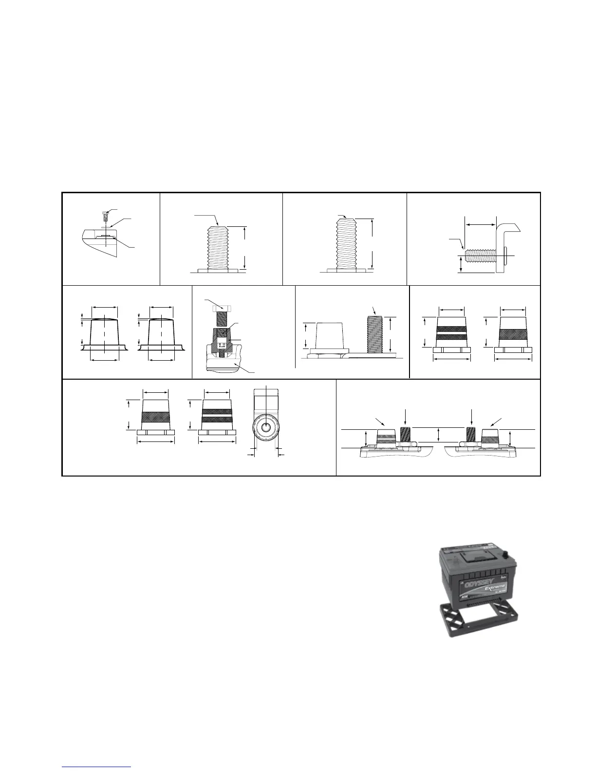
ALL OTHER MODELS PC370, PC950 & PC1100
PC1220 & PC1350
34M-PC1500 & 31M-PC215075/86-PC1230
25-PC1400
35-PC1400
34-PC1500
34/78-PC1500
65-PC1750
31-PC2150T
75-PC1230
75/86-PC1230
34/78-PC1500
78-PC1500
SAE TERMINALS PC2250 34R-PC1500
31-PC2150S
A. Bolt
B. Washer
C. Battery
A. Brass Post
B. Helicoil Insert
C. Accessory Bolt
3/8" Course Thread
(not included)
D. Battery
NOTE:
PC535 and PC625 Bolt installations
are in horizontal orientation.
A. 0.72" (18.2mm) MAX
B. 0.96" (24.5mm) MAX
B
A
C
M6 x 1
THREAD
0.43"
(11.0mm)
0.732"
(18.59mm)
0.568"
(14.43mm)
POSITIVE MARINE STUD
3/8-16 THREAD
NEGATIVE MARINE STUD
5/6-18 THREAD
POSITIVE SAE
TERMINAL
NEGATIVE SAE
TERMINAL
0.568"
(14.43mm)
0.732"
(18.59mm)
B
A
NTS
0.74"
(18.8mm)
3/8-16 UNC
THREAD
PC1800-FT
FRONT TERMINAL
POSITIVE
TOP TERMINALS SIDE TERMINAL
1.00"
(25.4mm)
0.53"
(13.5mm)
3/8-16 UNC
THREAD
0.768"
(19.5mm)
0.689"
(17.5mm)
0.039"
(1.0mm)
0.669"
(17.0mm)
0.630"
(16.0mm)
0.705"
(17.9mm)
0.669"
(17.0mm)
0.039"
(1.0mm)
NEGATIVE POSITIVE NEGATIVE
A
B
C
D
NTS
0.732"
(18.6mm)
0.677"
(17.2mm)
0.813"
(20.7mm)
0.732"
(18.6mm)
0.614"
(15.6mm)
0.813"
(20.7mm)
POSITIVE
0.732"
(18.6mm)
0.677"
(17.2mm)
0.813"
(20.7mm)
NEGATIVE
0.732"
(18.6mm)
0.614"
(15.6mm)
0.813"
(20.7mm)
3/8-16
UNC-2B
0.34 DEEP
0.85"
1.12"
DIN TERMINAL 3/8-16 UNC THREAD
NOTE: See SAE terminal drawing for detailed dimensions
1. Using proper procedures as recommended by the vehicle manufacturer, carefully disconnect the cables from
your old battery and remove it from the vehicle. Return the spent battery to the battery dealer for proper recycling.
2. Inspect existing battery cables for corrosion, acid damage or insulation deterioration. Replace if deterioration
is present.
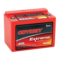
3. Position your ODYSSEY battery in the battery holder and fasten firmly to the vehicle.
• Optional height adapter may be used on 34-PC1500 models for installations
where a group 24 or group 27 is required. Snap the adapter securely into place on the
bottom of the battery. The 34R-PC1500 model with this adapter may be used to
replace a group 24F or 27F.
4. Connect the positive cable from your ignition to the Positive (+) terminal.
5. Connect the negative cable from your engine or chassis to the Negative (-) terminal.
6. Torque the bolt, screw or nut per the specification noted in table. If you’re using the Accessory Bolt (C), hold the Brass
Post (A) with vise grips and counter torque. Do the same with General Motors
®
automotive battery cable installation.
NOTE: This is a valve regulated sealed battery and never needs to have water or electrolyte (acid) added.
Warranty will be void if opened!
Publication No. 2602-0232, Rev. 11 - February 2013www.odysseybattery.com
3
INSTALLATION
Your ODYSSEY
®
battery is normally ready to install right out of the box! Measure the battery voltage; if it is 12.65
volts or greater, install; if less, then refer to the charging section.
ANY OF THE FOLLOWING WILL VOID YOUR WARRANTY:
• EXPOSING BATTERY TO OIL, ORGANIC SOLVENT, ALCOHOL, DETERGENT, STRONG ACIDS, STRONG
ALKALIS, PETROLEUM-BASED SOLVENT OR AMMONIA SOLUTIONS
• REMOVING THE LABELED COVER
• REMOVING OR DESTROYING THE BATTERY’S DATE CODE
DO NOT SHORT CIRCUIT YOUR ODYSSEY
®
BATTERY'S TERMINALS!
Remove any metallic items such as watches, bracelets and other personal jewelry to ensure safe installation.