EasyManua.ls Logo

Oilon S 180 - User Manual

Oilon S 180
68 pages
Print Icon
To Next Page IconTo Next Page
Loading...
CHS01 1951EN
19 December 2019
Installation and operation manual
ChillHeat S 180 – S 2000
Read these instructions carefully before installation, use, or maintenance
Question and Answer IconNeed help?

Do you have a question about the Oilon S 180 and is the answer not in the manual?

Overview

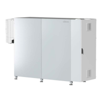
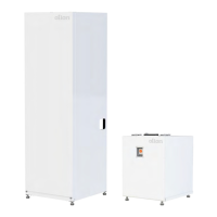
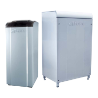
The Oilon ChillHeat S 180 – S 2000 is a heat pump designed for both heating and cooling applications, offering energy-efficient solutions for various environments. It can function as a dedicated cooling or heating unit, or as a combined solution, making it versatile for different operational needs. The system is based on the vaporization and condensation of a refrigerant circulating within the pump, utilizing three closed circuits: cooling, refrigerant, and heating.

Function Description:

The ChillHeat pump collects heat energy through its cooling circuit. As fluid travels through this circuit, it absorbs heat, causing its temperature to rise. This heat energy is then transferred to the refrigerant in the evaporator, causing the refrigerant to vaporize. The gaseous refrigerant is then compressed, increasing its pressure and temperature. This high-pressure, high-temperature gaseous refrigerant is directed to the condenser, where it releases its heat energy into the water of the heating circuit. As the refrigerant cools and releases heat, it condenses back into a liquid. Finally, the liquid refrigerant passes through an expansion valve, which lowers its pressure and temperature, preparing it to re-enter the evaporator and complete the cycle.

The heat pump can be used in combined solutions, such as data centers, where both cooling for server rooms and heating for office areas are required simultaneously. It can utilize various heat sources, including recovered waste heat from refrigeration plants, outdoor air (with an outdoor cooling unit), municipal or industrial waste waters, industrial process waters, flue gases from power plants, and heat from ground or waters. The recovered heat can be channeled into district heating networks, improving overall plant efficiency and heat output.

Important Technical Specifications:

The ChillHeat S 180 – S 2000 series offers a range of models with varying dimensions, weights, and refrigerant capacities.

  • Dimensions (without cover and extra legs):

    • S 180 - S 490: Height 2091 mm, Width 2723 mm, Depth 911 mm.
    • S 600: Height 1900 mm, Width 4700 mm, Depth 1000 mm.
    • S 800: Height 1900 mm, Width 4700 mm, Depth 1000 mm.
    • S 1000 - S 1200: Height 2100 mm, Width 4700 mm, Depth 1100 mm.
    • S 1500 - S 2000: Height 2190 mm, Width 5500 mm, Depth 1600 mm.
  • Weight:

    • S 180: 2300 kg
    • S 280: 2900 kg
    • S 380: 3600 kg
    • S 490: 4000 kg
    • S 600: 3200 kg
    • S 800: 4000 kg
    • S 1000: 4500 kg
    • S 1200: 5300 kg
    • S 1500: 6500 kg
    • S 2000: 7500 kg
  • Electrical Connections: All models typically require 3L/PE/400 VAC 50 Hz. Fuse sizes vary by model:

    • S 180: 250 A
    • S 280: 355 A
    • S 380: 400 A
    • S 490: 500 A
    • S 600: 2x3x400 A
    • S 800: 2x3x400 A
    • S 1000 - S 1200: 2x3x630 A
    • S 1500: 2x3x800 A
    • S 2000: 2x3x1000 A
  • Refrigerant: R134A is used across all models. Refrigerant fill quantities vary:

    • S 180: 30 kg
    • S 280: 55 kg
    • S 380: 60 kg
    • S 490: 95 kg
    • S 600: 2 x 75 kg
    • S 800: 2 x 100 kg
    • S 1000: 2 x 135 kg
    • S 1200: 2 x 170 kg
    • S 1500: 2 x 240 kg
    • S 2000: 2 x 350 kg
  • Water or Brine Circuits: Minimum water/brine outlet temperature from the evaporator is -15 °C. Maximum water/brine inlet temperature to the evaporator is 50 °C.

  • Refrigerant R1234ze(E) Information: If the product contains R1234ze(E) (GWP: 1, safety group A2L), it must be equipped with a ventilated enclosure system or installed in a special machinery room conforming to EN 378-3 (2016) clause 5. This refrigerant is mildly flammable but nonflammable for handling and storage below 30 °C. Local building codes and safety standards must be followed for installation.

Usage Features:

The ChillHeat heat pump is equipped with an automatic control system that manages both heating and cooling functions. The system includes a built-in automation system, sensors, and a control panel for monitoring and changing settings, as well as browsing and resetting error notifications. The control program supports common field bus protocols (Modbus, Profibus) and offers remote monitoring and programming.

The user interface is graphical and touch-screen based, with three user levels:

  • User: Access to basic settings, local or remote control, chill or heat mode, trends, and date/time settings.
  • Expert: All User features, plus access to alarm min/max times and compressor measurement values in advanced settings.
  • OEM: Manufacturer-only access to factory settings.

Users can change setpoint values, start/stop the heat pump, acknowledge alarms, and view trends without logging in. The system allows for setting time zones, dates, and languages. It also provides detailed views of heat pump operation, including evaporator and condenser buffer screens, measured values, motor status, and PID controller values.

Maintenance Features:

Regular checks and maintenance are crucial for the safe and efficient operation of the ChillHeat heat pump.

  • Safety Precautions: Installation, commissioning, operation, and maintenance must be carried out by authorized and trained personnel. DANGER symbols indicate risks of bodily harm or lethal injury, while CAUTION signs indicate potential damage to the device.
  • Transportation and Storage: The heat pump must be transported and stored vertically using appropriate lifting tools. It should be stored in a dry place at a minimum temperature of +5 °C.
  • Installation Site Requirements: The installation surface must be horizontal and even, with all feet firmly attached to the floor. The pump should be protected from rain and direct sunlight, in a well-lit and ventilated machine room (10-40 °C). Minimum space requirements are 800 mm (left/right/front) and 400 mm (back/top) for maintenance access.
  • Refrigerant Circulation: Safety valves are equipped to release excess pressure. Discharge piping should be routed to a safe location to prevent danger to people or property.
  • Commissioning: This involves checking hot and cold circuits for correct connections, flow direction, and component installation. Pressure relief valves must be installed, and pipe insulation and support checked. Electrical connections must be verified, including fuse sizes and control voltage. A preliminary work form for commissioning must be completed.
  • Leakage Test: A thorough leakage test is required, especially for systems using R1234ze(E) refrigerant. The refrigerant should not be mixed with air for leak testing.
  • Parallel Units: The system supports setting up parallel units, requiring adjustment of IP addresses and flow distribution.
  • Distribution Condenser/Subcooler: Procedures are provided for setting up flow distribution in systems with multiple condensers or subcoolers.
  • Regular Check and Maintenance: The manual specifies maintenance intervals based on the amount of refrigerant:
    • < 50 ton CO2 equiv.: 12 months (normal), 24 months (leak detector)
    • 50 – 500 ton CO2 equiv.: 6 months (normal), 12 months (leak detector)
    • 500 ton CO2 equiv.: 3 months (normal), 6 months (leak detector)

  • Troubleshooting: The manual includes a comprehensive list of failure symptoms, probable causes, and recommended actions for troubleshooting common issues, such as refrigerant gas detection, no cold water flow, electrical supply phase faults, and compressor problems.
  • Alarm Monitoring: Active alerts, warnings, and alarms are displayed on the Active notification page, allowing users to reset alarms and view alarm history.

Oilon S 180 Specifications

General IconGeneral
BrandOilon
ModelS 180
CategoryHeat Pump
LanguageEnglish

Related product manuals