EasyManuals Logo

Oldham OLC 100 User Manual

Oldham OLC 100
76 pages
To Next Page IconTo Next Page
To Previous Page IconTo Previous Page
Page #16 background imageLoading...
Page #16 background image
16
OLC(T) 100
User manual
Electrical power supply
Type of detector
Supply (V DC)
Maximum
current (mA)
Power consumed
(mW)
OLCT 100 XP HT
15,5 to 32
110
1705
OLCT 100 XP LEL
15,5 to 32
100
1550
OLCT 100 XPIR
15,5 to 32
80
930
OLCT 100 XP EC
11 to 32
23,5
260
OLCT 100 IS EC
11 to 32
23,5
260
OLCT 100 XP SC
15,5 to 32
100
1550
OLC 100 (VQ1)
By Oldham
Simtronics
controller
340
(1)
OLC 100 (4F)
By Oldham
Simtronics
controller
370
(1)
(1) Depends on the gas controller
Location of the detector
Depending on the density of the gas to be detected or the application, the detector
shall be positioned at the ground level, or on the ceiling at the same height as the
airflow, or near to the air extraction ducts. Heavy gases may be detected at the
ground level, while light gases will be found at ceiling height. Gas densities are
provided on page 28.
Detector positioning
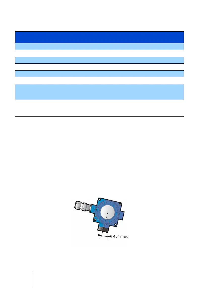
The detector shall be installed with the detector sensor pointing downwards.
Any tilt of more than 4 from the vertical will lead to an inaccurate measurement.
014
Figure 5 : sensor pointing downwards and m aximum tilt angle

Questions and Answers:

Question and Answer IconNeed help?

Do you have a question about the Oldham OLC 100 and is the answer not in the manual?

Oldham OLC 100 Specifications

General IconGeneral
BrandOldham
ModelOLC 100
CategoryGas Detectors
LanguageEnglish

Related product manuals