16
GB
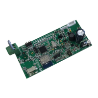
2.2 Position of the connection cable
Connectthekit'scommunicationcabletotheappropriateconnectoronthecard(Fig.1Ref.A)accordingtoyour
appliancemodel:
• UnicoInverterandUnicoAirInverter,connectthecabletoconnectorCN5(Fig.1Ref.E).
• UnicoSmart,UnicoAir,connectthecabletoconnectorCN1(Fig.1Ref.D).
2.3 Choosingtheinterfaceinstallationposition
2.3.1 UNICOSMART,UNICOINVERTERMODEL
TheslotinwhichtohousetheB1015cardislocatedbehindthemachineonthetopleft.
• Disconnectairconditioner'spowersupply.
• Removethemachinefromthewallbracket.
• Slideoutthelowercover(Fig.2Ref.A).
• Slideouttheuppercover(Fig.2Ref.B).
• Unscrewthe6screwsthatlockthefrontcover(Fig.2Ref.C).
• Removethefrontcover(Fig.2Ref.D).
• Removetherearguardonthetopleft(Fig.3Ref.A)byunscrewingitstwoscrews(Fig.3Ref.B).
• PlacetheB1015cardintotheappropriateslotandthentightenitsscrews(Fig.3Ref.C)tosecureit.
• Connectthecommunicationcabletotheserialportlocatedunderneaththeelectricalpanel(Fig.4Ref.A).
• Routethewiringontheleftsideoftheelectricalpanel(Fig.4).
• Closetherearguard(Fig.3Ref.A)andtightenthescrews(Fig.3Ref.B).
• Retthemachine'sfrontcover(Fig.2Ref.D)andsecureeverythingwiththesixscrews(Fig.2Ref.C).
• Rettheupperandlowerinterlockingcover(Ref.2AandB).
• Retthemachineonthewall.
2.3.2 UNICOAIRMODEL
TheslotinwhichtohousetheB1015cardislocatedonthemachine'sfrontpanelonthetopright.
• Disconnectairconditioner'spowersupply.
• Removetheltersabovetheevaporatingunit(Fig.5Ref.A).
• Removethe3screwsindicatedinFig.5.
• RemovethemachinefromitsjointsbyslidingitoutandturningitasshowninFig.6.
• PlacetheB1015cardintotheappropriateslot(Fig.7)andthentightenitsscrews(Fig.7Ref.A)tosecureit.
• Connectthecommunicationcabletotheconditioner'sserialconnector(Fig.7Ref.C)andtotherespective
connectorontheB1015card(Fig.7Ref.B)asspeciedinparagraph2.2.
• Retthemachine'sfrontcover(Fig.6)andsecureeverythingwiththe3screws(Fig.5).
• Inserttheltersabovetheevaporatingunit(Fig.5Ref.A).
• Retthemachineonthewall.
 Loading...