LB51100 Installation and User Manual
Shenzhen Olipower Energy & Automation Technology., Ltd
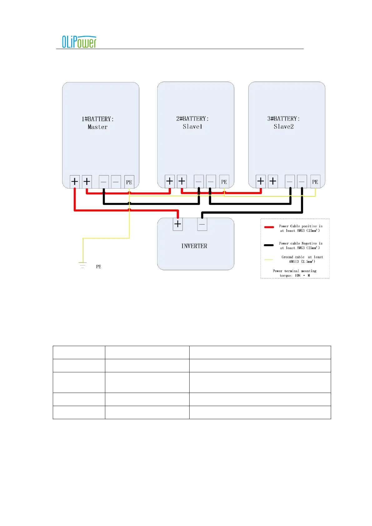
5.4.4.4 Power cable connection
Attention: The following figure is only the power cable connection diagram, the specific connection. Please
refer to the object for specific connection.
6 Battery box activate and shutdown
6.1 Panel buttons and LEDs meaning
Attention: the drawing is for reference only, please take the material as the standard.
Function or indication status
Control battery box on or off
Running indicator light (green)
When the battery box is running normally, it always
bright
Low battery indicator (yellow)
When the battery is low(SOC<5%), it is always bright.
Fault indicator light (red)
Flashing alarm when the battery box is faulty
6.2 The operation steps of the battery box works alone
6.2.1
Start battery box
Short press the power button (1S), RUN light on, switch on the isolator between the battery and inverter., battery box is
activated normally.
6.2.2
Shut down battery box
Long press the power button (5S), RUN light off, switch on the isolator between the battery and inverter, battery box is shut