5.3.1
Product dimensions
See Appendix 2.
5.3.2
Installation method
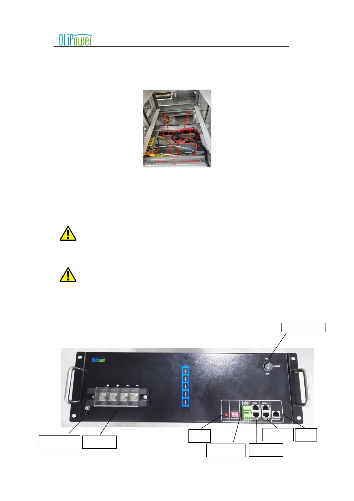
5.3.2.1 Cabinet Installation
The positions of bolts are shown in the picture, which are anchored into ground.
5.3.2.2 Rack mounting Installation.
After the Cabinets installed firmly and reliably, the battery box is pushed from side to side along the wall until
the mounting card on the battery box is placed in the proper position of the rack mounting position.
Information:
Rack -mounted installation is suggested that the external connection line of the battery box should be connected
first and then installed.
Information: When installing the battery box, please work together to avoid product damage or
personal injury.
5.4 Wiring definition
5.4.1
Terminal function and definition
The bottom terminal layout is shown in the following figure: