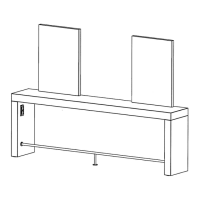
MO Square Doppelplatz
Electrical conditions provided by customer:
- if plug sockets and / or mirror lighting wished
Plug sockets EU: double cover with 2 sockets
Plug sockets GB: double cover with 1 socket + 1 lid
> no
internal fuse! Electrical connection and
f
use must be made on-site due to GB
t
echnical regulations!
Free standing unit:
Electrification from floor:
Floor cable outlet: > see illustr. 1, Pos. (A)
Square without lighting:
> 2 separate fused circuits necessary
for 2 double sockets:
>
2 cables NYM 3x1,5mm
2
, or
1 cable NYM 5x1,5mm
2
under L/H or R/H side from floor,
each approx. 2500 mm long.
Square with mirror lighting:
> 3 separate fused circuits necessary
for 2 double sockets + mirror lighting:
>
3 cable NYM 3x1,5mm
2
or
1 cable NYM 5x1,5mm
2
+ 1 cable NYM 3x1,5mm
2
under L/H or R/H side from floor,
each approx. 2500 mm long,
therefrom 1 lead for mirror lighting with centrically
customer switch.
Wall standing unit:
Electrification from wall:
Wall cable outlet: > see illustrr. 2, Pos. (B)
Square without lighting:
> 2 separate fused circuits necessary
for 2 double sockets:
>
2 cables NYM 3x1,5mm
2
from wall or
1 cable NYM 5x1,5mm
2
each approx. 1000 mm long
> height 760 mm from floor
Square with mirror lighting:
> 3 separate fused circuits necessary
for 2 double sockets + mirror lighting:
>
3 cable NYM 3x1,5mm
2
or
1 cable NYM 5x1,5mm
2
+ 1 cable NYM 3x1,5mm
2
therefrom 1 lead for mirror lighting with centrically
customer switch,
each approx. 1000 mm long
> height 760 mm from floor
Assembly instruction:
1. Mount the sides: > see illustr. 3
§ Lay the styling unit onto the floor, top side down
on a suitable soft support.
§ Place the sides with the mounting brackets (G) down
to the tabletop and fix it to the tabletop by means
of 6 chip board screws 3,5 x 16 (R/H side with
sockets, L/H side without sockets).
Meanwhile push the connection cables of plug sockets
outside of the lower edge of side.
2. Mount blow-dryer holder (FH) (Option):
> se
e illustr. 3 + 4
§ Fix mounting block (H) under worktop.
§ Unscrew nut, put away guide ring.
Mount fixing plate to mounting block.
§ Fix guide rings together with blow dryer ring in
reverse order.
3. Set up styling station:
3.1 Unit with electrification from floor: > see illustr. 5
§ Attach the fixing strips (J) to the floor, distance of
drillings (D) see illustr. 1, meanwhile push the cables
through the cutout of the fixing strip.
§ Tilt the styling unit at 90° to the floor and place the sides
behind the fixing strips.
§ Push the cables from floor down there into the side and
pull out at the top under the worktop.
§ Place styling unit with sides onto fixing strips.
PLEASE NOTE: make sure that the cables are not
pinched!
> So
the styling unit is secured against slipping and
t
he cables are secured against shearing.
3.2 Unit with electrification from wall:
§ Place styling unit in front of wall without fixing strips.
4. Mount footrest (Option): > see illustr. 6
§ Mark the fixing points for footrest FS) to the sides.
§ Place the footrest between the sides and fix them by
mans of each 3 screws 3,5 x 16.
§ Mark the drillings for floor mounting to the floor, than
detach the footrest.
§ Make drillings of Ø 8mm into the floor for dowel fixing.
§ Fix the footrest again to the sides, fix the footrest to the
floor by means of 2 universal dowels + 2 screws 4,5 x 45
GB
 Loading...