Besides the terminals that were described up to now the panel also has the following outputs :
24V_M: A 24VDC output that is interrupted in the event of a panel reset. It is mainly used for powering gas
detectors or other devices that need an interrupted power supply when the panel is resetting. If this output
is short circuited then the LED marked 'General fault' is lighted.
24V_P: A 24VDC power output that is not interrupted in the event of a reset. It can be used to power
electromagnetic door latches.
Relay Alarm : Voltage free relay contacts are activated when there is an alarm condition.
Relay Fault : Voltage free relay contacts are deactivated when there is an fault condition.
Relay AUX : Voltage free relay contacts that by default when one zone is in alarm condition.
ATTENTION: The relays are rated at 30VDC and 5A maximum. No 230VAC signals can be connected
to these relays.
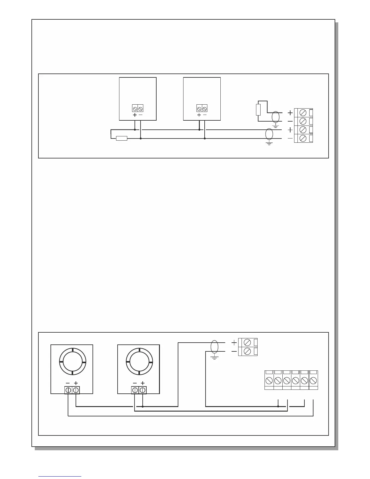
Siren - Sounder Connections
Each panel offers 2 independent circuits for connecting sirens, bells or other devices that need 24VDC in order
to operate. Each circuit can supply a maximum of 300mA. Each terminal block by default has a pre-installed
terminal resistor (8Κ2). This terminal resistor is either removed and installed on the last siren of the line or is
left on the terminal block if the circuit is not used.
The connections of both circuits are identical.
Figure 5. Connecting 2 BS-531 sirens to the ALARM 2 output. This connection requires polarity.
BS-531
Siren with
Beacon
BS-531
Siren with
Beacon
8Κ2
ALARM1 A LARM2
8Κ2
Terminal
Resistor
Terminal
Resistor
Figure 6. Connecting 2 electromagnetic door latches BS-510/24 to the panel.
ALARM FAU LT
24V_P
C C
NO NONC NC
24V DC 24V DC
BS-510/24BS-510/24
Page 6 from 10 921163600_09_022