Battery disposal
I s not allowed to discard batteries into common trash bins, they must be discarded onlyt i in
battery recycling points.
Warnings
1. Service and maintence activities should be done only when the device is disconneted from
the mains power supply and the battery.
2. During the installation the connections to the mains power supply and the battery must be
done after all other connections are finished.
3. The panel connection with the mains supply must be done via a10A external fuse or an
automatic circuit breaker rated at 10A.This fuse has to be a separate, labeled fuse.
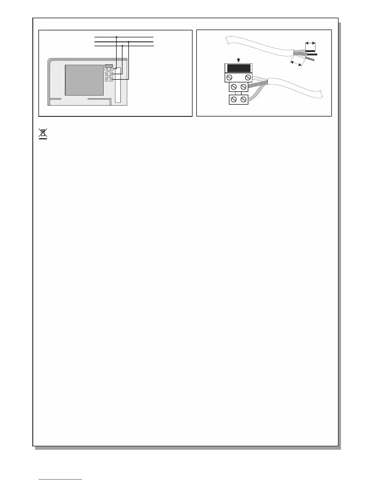
4. Always use cables with double insulation.
5. The diameter of the cable must be at least 1mm.(Figure 9)
6. The inner insulation of each cable must not be cut more than 1cm (Figure 9)
7. The outer insulation must not be cut more than 1cm away from the internal insulation.
8. The panel's internal fuse is T630mAL250V with 5x20 dimensions.
9. The batery fuse is a resetable fuse 900mA inside the panel.
Initial Installation
When the connections to zones, sirens and other required outputs are finished then we must connect the mains
power supply. In order to aid the installer during the initial installation, the panel offers a special configuration.
This configuration is entered by setting MODE switch 1 to the ON position. After entering this mode the panel
conducts an auto reset and the 'Power', 'Zone disable' and 'General disable' LEDs blink. The special functions
that aid in working out various problems that might arise are:
When a zone has an open circuit then the internal buzzer sounds and the corresponding LED lights. If the
problem is corrected then the buzzer is deactivated and the LED is turned off.
When a zone has a short circuit then the internal buzzer sounds and the corresponding LED blinks. If the
problem is corrected then the buzzer is deactivated and the LED is turned off.
When a siren output has an open circuit then the internal buzzer is activated and the corresponding fault LED
lights. If the problem is corrected then the buzzer is deactivated and the LED is turned off.
When a siren output has a short circuit then the internal buzzer sounds and the corresponding LED blinks. If the
problem is corrected then the buzzer is deactivated and the LED is turned off.
When a battery fault exists then the 'Batt fault' LED lights and the 'Power fault' LED blinks. If the problem is
corrected then the LEDs are deactivated.
If all the problems are corrected and the installation is operating normally then the MODE switch 1 must be placed
in the OFF position. The panel conducts an auto-reset and is ready for operation.
Walk - Testing
By using a special operation mode we can conduct a walk test of the system. To enter walk-test mode set the MODE switch
1 to the ON position. The 'Power', 'Zone disable' and 'General disable' LEDs blink. If an alarm is manually given by either
activating a BS-536 call point or by activating a smoke detector with smoke or simulated smoke particles the
corresponding Alarm LED of the zone will light and the siren will sound for 2 seconds. Using this method we can test the
operation of the zones.
After finishing the walk test set the MODE switch 1 to the OFF position. The panel conducts an automatic reset and enters
normal operation mode.
Optional Function of EN 54-2.
The optional function which is provided by the panel is the fire alarm devices paragraph 7.8 of EN 54-2 and delays to
outputs (paragraph 7.11 of EN 54-2).
Design
Components of the panels have been selected for the intended purpose, and are expected to operate within their
specification when the environmental conditions outside the cabinet of the panel comply with class 3k5 of
EN 60721-3-3:1995.
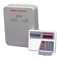
Figure 8. Panels connection with 220-240V AC
220-240V AC
L
N
1 cm
Fuse: T630mAL250V (5x20)
1 cm
Figure 9. Panels connection with 220-240V AC
PE
Page 8 from 10 921163600_09_022
 Loading...