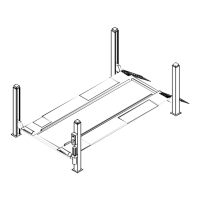
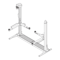
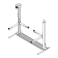
Po si zio na re le co lon ne all’e stre mi tà
del le tra ver se (pos. 5-6, Fig.39) se
-
guen do la nu me ra zio ne e lo sche ma
del la fi gu ra 39.
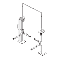
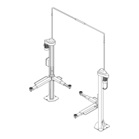
In fi la re dall’al to del le co lon ne le aste
di si cu rez za (12) fa cen do le pas sa re
tra la par te po ste rio re del le tra ver se
(5-6) ed i per ni di gui da (13) come in
fi gu ra 43.
Ve ri fi ca re che le aste di si cu rez za
sia no di rit te.
Mon ta re le aste di si cu rez za con I
bor di ar ro ton da ti del le aso le ver so
la par te fron ta le del le co lon ne.
Fig.43
Sede di in se ri men to dell’asta di si cu rez za
Bloc ca re quin di l’e stre mi tà in fe rio re del le aste (12) con le viti TE
M10x25 (30) e le ro set te Ø10x30 (29) come mo stra to in fi gu ra 44.
To glie re i dadi M20 (pos.25, Fig.42) e le ro set te Ø21x37(26) dall’e -
stre mi tà del le funi e in se ri re i ter mi na li (19) del le stes se ne gli ap po -
si ti fori del le pia stre su pe rio ri del le co lon ne.
Fig.42: av vi ta re sui ter mi na li (19) i dadi (25) e le ro set te (26). Du -
ran te que sta ope ra zio ne é im por tan te ve ri fi ca re che i sen so ri (17)
sia no cor ret ta men te po si zio na ti sul le funi (18) fi gu ra 45.
Fig.44 Bloc cag gio dell’a sta di si cu rez za
Fig.44 Sa fe ty rod loc king
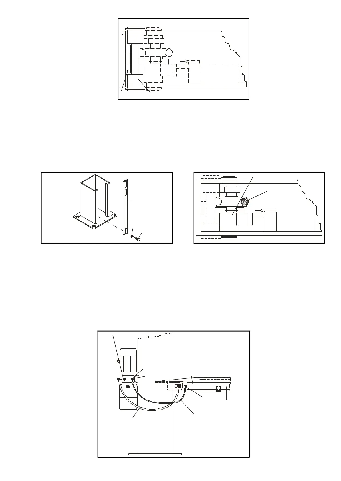
ALLACCIAMENTO IMPIANTO IDRAULICO
Fig.46: col le ga re il tubo in gom ma alta pres sio ne (20) al rac cor do
del tubo me tal li co sul la pe da na fis sa (7) ser ran do lo a fon do. To -
glie re il tap po (21) dal cor po del la cen tra li na (10), av vi ta re il rac cor -
do (22) e in se ri re nel lo stes so il tubo di sfia to (23) pre ce den te men -
te col le ga to al rac cor do po sto sul fon del lo del ci lin dro di sol le va -
men to (24).
Fig.46 Al lac cia men to im pian
-
to idrau li co
Po si tion the posts at the end of the
cross- pi e ces (pos. 5-6, fig.39) ob ser
-
ving the num be ring and the lay- out
shown in fi gu re 39.
Fit the sa fe ty rods (12) from the top
of the posts, in ser ting them betwe en
the rear face of the cross- pi e ces
(5-6) and the gui de pins (13) as
shown in fi gu re 43.
Check the Sa fety rods are stra ight.
Fit the Sa fety rods with the ro un -
ded ed ges of the slots to wards the
front of the posts.
Fig.43
Hou sing for fit ting sa fe ty rod
Now se cu re the bot tom end of the rods (12) using M10 x 25 H.H.
screws (30) and the 10 x 30 was hers (29) as shown in fi gu re 44.
Re mo ve the M20 nuts (pos.25, fig.42) and the 21 x 37 was hers
(26) from the ends of the lif ting cables and in stall the ter mi nal
blocks (19) in the re le vant ho les on the top pla tes of the posts.
Fig. 42: screw the nuts (25) and was hers (26) onto the ter mi nal
blocks (19). Du ring this pro ce du re make sure that the sen sors (17)
are cor rectly po si tio ned on the lif ting cables (18) as shown in fi gu re
45.
Fig.45 Po si zio na men to dei sen so ri fune
Fig.45 Po si tio ning of lif ting cab le sen sors
HYDRAULIC SYSTEM CONNECTION
Fig.46: con nect high pres su re rub ber hose (20) to the union of the
me tal pipe on the fixed plat form (7) and tigh ten it ful ly down. Re mo -
ve the plug (21) from the body of the hydrau lic power unit (10),
screw in union (22) in its pla ce, and fit the breat her pipe (23) that
was pre viously con nected to the union on the bot tom of the lift
cylin der (24).
Fig.46 Hydrau lic sy stem
27
12
13
5-6
12
29
30
17
18
10
21
22
20
23
7
24
22
 Loading...