CAP.5 FUNZIONAMENTOEUSO
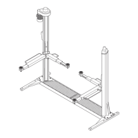
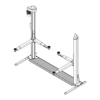
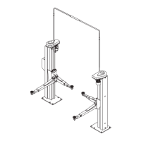
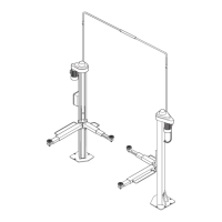
Fig.59
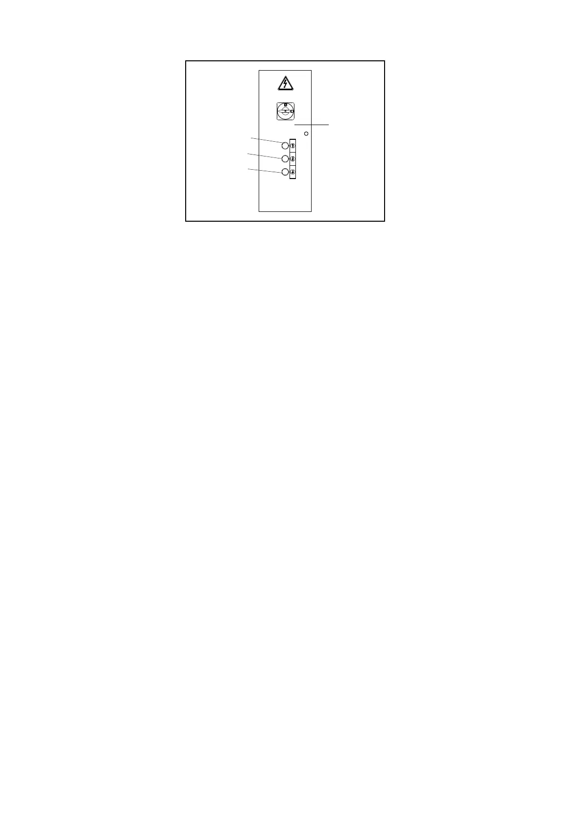
Icomandiattraversoiqualisiutilizzailsollevatoresono:
INTERRUTTOREGENERALE(QS)
POSIZIONE0:ilsollevatorenonéintensione,épossibilel’acces
-
soall’internodelquadro;éaltresìpossibilelucchettarel’interruttore
perimpedirel’usodelsolllevatore.
POSIZIONE1:datensionealsollevatoreebloccalaportadelqua
-
drocontroapertureaccidentali.
PULSANTEDISALITA(SB1)
Tipo“uomopresente”,tensione24V;sepremutoazionalapompa
dellacentralinaidraulica.
PULSANTEDIDISCESA(SB2)
Tipo“uomopresente”,tensione24V;sepremutoazionaimagneti
disganciodeimartellettidisicurezzael’elettrovalvoladidiscesa
dellacentralinaidraulica.
PULSANTEDISTAZIONAMENTO(SB3)
Tipo“uomopresente”,tensione24V;sepremutoazional’elettro-
valvoladidiscesadellacentralinaidraulica.
SOLLEVAMENTO
Ruotarel’interruttoregenerale(QS)inposizione1epremereil
pulsantedisalitafinoalraggiungimentodell’altezzadesiderata.
Durantelacorsa,lalevadicomandomartellettirestainposizione
diriposo(alzata)epertantoimartellettisiinserisconoautomatica
-
menteinogniasoladelleastedisicurezza.
STAZIONAMENTO
IncondizionidistazionamentoilcariconondeveMAIesseresoste
-
nutodallefuniportanti,madaimartellettidistazionamentoche
quindidevonoessereautomaticamenteinseritinelleasoledelle
astedisicurezza.
Unavoltaraggiuntal’altezzadesideratapremereilpulsantedista
-
zionamento(SB3).
L’arrestodelmovimentoavvieneautomaticamenteallorchéimar
-
tellettisiappoggianosulpianodellaprimaasolacheincontrano
duranteladiscesa.
DISCESA
Premereilpulsantedidiscesa(SB2)chesganciaautomaticamente
imartellettiedazional’elettrovalvoladidiscesa.
Ladiscesaverràarrestatadalmicrointerruttoredidiscesa.
PercompletareladiscesabisognarilasciareilpulsanteSB2epre
-
mereilpulsanteSB3,questapartedelladiscesavieneaccompa
-
gnatadaunsegnaleacusticocheavvertedelpericolodischiaccia
-
mentodeipiedi.
Seduranteladiscesalapiattaformaincontraun’ostacolocheim
-
pedisceilproseguimentodellacorsasihal’interventodeisensori
cheazionanoimicrodisicurezzaallentamentofuniconconse
-
guentearrestodelmovimento.
Inquestasituazioneépossibilecomandaresololasalita.Durante
lafasedidiscesalasicurezzacontrol’accidentalecadutadelvei
-
coloésempreassicuratadalmartellettocomandatodalsensoreal
-
lentamentofuni(azionatomeccanicamente).
CHAPTER5 OPERATING
PRINCIPLESANDUSE
Fig.59
Theliftoperatorcontrolsare:
MAINSWITCH(QS)
POSITION0:theliftisnotconnectedtotheelectricalsupply;you
canopenthecontrolpanelandinstallalockoutonthemainswitch
topreventunauthoriseduseoftheunit.
POSITION1:theliftisreceivingelectricalpower;thedoorofthe
controlpanelislockedandcannotbeopenedinadvertently.
LIFTBUTTON(SB1)
“Operatorpresent”type,24V;whentheLIFTbuttonispressedthe
hydrauliccontrolunitwillstartup.
LOWERINGBUTTON(SB2)
Alsothisbuttonis“operatorpresent”type,24V;whenpressed,it
activatesthereleasemagnetofthesafetywedgesandthelowe-
ringsolenoidvalveofthehydrauliccontrolunit.
STOPBUTTON(SB3)
Operatorpresent”type,24V;pressingtheSTOPbuttonactivates
theloweringsolenoidvalveinthehydrauliccontrolunit.
LIFTING
Setthemainswitch(QS)to1andpresstheLIFTbuttonuntilthe
liftreachesthedesiredheight.
Duringitstravel,thesafetywedgereleaseleverwillremaininthe
“rest”position(raised)sothatthewedgesautomaticallyengage
witheachslotofthesafetyrods.
STOPPING
Whenavehicleisstoppedintheelevatedposition,theloadmust
NEVER besupportedbytheliftcables,theloadmustinsteadbe
supportedbythestoppingwedgeswhichmustthereforebeenga
-
gedautomaticallyintheslotsonthesafetyrods.
WhenyoureachthedesiredheightpresstheSTOPbutton(SB3).
Themovementwillbehaltedautomaticallyassoonasthewedges
encounterthefirstsafetyrodslotsduringtheinitiallowering.
LOWERING
Presstheloweringbutton(SB2),whichautomaticallydisengages
thesafetywedgesandactivatestheloweringsolenoidvalve.Lowe
-
ringwillbestoppedbyloweringmicroswitch.Inordertocomplete
thelowering,thepushbutton(SB2)willhavetobereleasedand
pushbutton(SB3)willhavetobepressed.Inthelastpartofthelo
-
weringanaudiblealarmwillbeheardtopreventfromfoottreading
danger.
Iftheplatformshouldencounteranobstructionduringitslowering
thesensorsthatactivatetheliftcableslacksafetymicroswitches
willoperateandstoptheloweringmovement.
InthissituationonlytheLIFTcontrolisaccepted.Notethatduring
loweringcyclesprotectionagainsttheaccidentalfallingofthe
vehicleisprovidedbythesafetywedgecontrolledbytheliftcable
slacksensor(mechanicaloperation).
34
SB2
QS
SB1
SB3
 Loading...