FM Transmitter
Sistemas Electrónicos S.A EM 250 COMPACT DIG
Technical Manual - v1.1 - February 2006 15
2.1 Introduction.
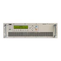
The EM-250 COMPACT DIG transmitter comprises 5 or 6 internal modules, as can be seen in the
general upper view (Figure 1-4) and in the General Wiring Diagram (in next pages). Main units are the
following:
The Main Audio Processor Board.
The Microcontroller Unit and Display Board.
The Stereo Encoder Module (optional).
-The RF Exciter Board.
The RF Power Amplifier Module.
The Switching Regulated Power Supply Units (Main and Auxiliary).
For the detailed description of each module on the following pages, always refer to the corresponding
electrical diagram, included in this section.
Note
: the manufacturer reserves the right to change any component value due to production
adjustments.
THIS SECTION IS ONLY AIMED TO GENERAL EXPLANATION,REFERENCE AND SERVICE PURPOSE BY SKILLED
PERSONNEL. AS EXPLAINED IN THE PREVIOUS SECTIONS, INTERNAL ADJUSTMENTS ARE NOT REQUIRED
DURING NORMAL OPERATION. TAMPERING WITH INTERNAL SETTINGS VOIDS THE WARRANTY, MAY HARM THE
APPARATUS AND JEOPARDIZE THE GUARANTEED PERFORMANCE.
DUE TO THE TECHNOLOGY USED,MOST MODULES AND ESPECIALLY THOSE IN SMT ARE NOT INTENDED TO BE
REPAIRED IN CASE OF FAILURE AND MUST BE REPLACED WITH NEW ONES.