4
UTILIZZO USE
20
OMCA S.r.l - Via Curiel, 6 - 42025 - Cavriago (RE) - ITALY
Telefono: +39 0522 943502 / +39 0522 943503 - Website: www.omcasrl.it - E-mail: info@omcasrl.it
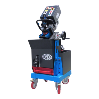
La POSIZIONE DI 0 = Cutter Position e i valori che determinano la
dimensione dello smusso sono visualizzati sul display (Fig.4.5 pos.C).
1) Accertarsi che l’indicatore di posizione visualizzi la misura
assoluta (sullo schermo in basso a sinistra non deve essere
presente nessuna scritta) in caso contrario premere il pulsante
ABS-REL (Fig.4.6A);
2) Allentare la leva di bloccaggio regolazione smusso (Fig.4.5
pos.A);
3) Ruotare il volantino (Fig.4.5 pos.B) sino a visualizzare la misura di
0.0 (Fig.4.6A);
4) Regolare la profondità di smusso desiderato.
Al termine dell’operazione stringere la leva di bloccaggio
regolazione smusso (Fig.4.5 pos.A).
The POSITION OF 0 = Cutter position and the values that determine
the chamfer dimension are showed on the display (Pic.4.5 pos.C).
1) Make sure that the indicator of position shows the absolute
measure (no writing must appear on the display in the bottom left
corner), otherwise push the button ABS-REL (Pic.4.6A);
2) Loosen the adjustment chamfer locking lever (Pic.4.5 pos.A).
3) Turn the hand-wheel (Pic.4.5 pos.B) until you see the measure
0.0 (Pic.4.6A);
4) Adjust the chamfer depth desired.
At the end of the operation tighten the chamfer adjustment locking
lever (Pic. 4.6 pos.A).
4.6A
VISUALIZZAZIONE / SETTAGGIO DISPLAY VIEW / DISPLAY SETTING
 Loading...