5. Use and maintenance manual B01.26 - B02.40 - B02.10
San Maurizio C.se - 01/09/2021 www.omcr.it
G
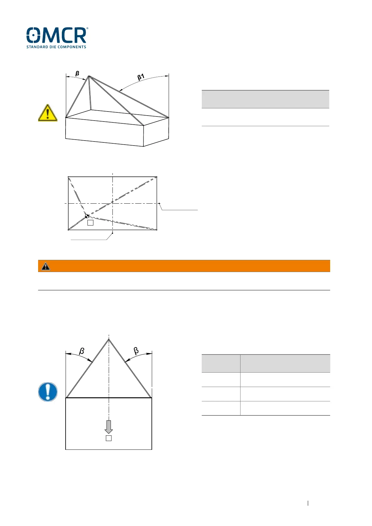
3.2.2 - OVERTURNING
G
G = Die load center
β = Rope angle from vertical
ANGLE
REDUCTION FACTOR OF THE
NOMINAL CAPACITY LOAD
0°≤
β≤40°
0.6
40°<
β≤50°
0.5
50°<
β≤60°
0.4
SYMMETRIC SLING EXAMPLE
(RECOMMENDED CONDITION)
NOTE: overturning with β>60° is not provided.
DIE AXIS
DIE AXIS
G = Die load center
β = Minimum rope angle from vertical
β1 = Maximum rope angle from vertical
REDUCTION FACTOR OF THE NOMINAL
CAPACITY LOAD
0.5
ASYMMETRIC SLING EXAMPLE
(β1>β)
WARNING
Failure to observe the regulations listed in these instructions can cause the load to fall.