The starter wire will read Positive 12 Volts only when ignition key is in "start" position
(cranking the engine). Cut this wire at a suitable location. Confirm that this is the correct wire
by turning the ignition switch to the "start" position. The starter should not engage. Connect
the starter disable socket's Red wire to the ignition switch side. Connect the starter disable
socket’s White wire to the starter solenoid side. Be sure that good, solid electrical connec-
tions are made as this generally is a high amperage circuit.
The diagram below shows a typical dash-mounted ignition
switch, and the Orange,
Red and White wire
connections, and the
diagram on the
previous page
illustrates the
layout of a column-
mounted ignition switch.
Orange, Red & White Wires
Connection: This diagram shows
a typical dash-mounted ignition
switch; diagram on previous page
shows a typical column-
mounted ignition switch.
Dash-mounted
Ignition
Switch
Relay
Starter Disable White
wire to the
Starter Solenoid
side of the cut
wire.
Starter
Solenoid
Starter
Motor
Starter Disable Red
wire to the Ignition
Switch side of the
cut wire.
Starter
Disable
Socket
5-Pin Connector
Socket
Orange
wire
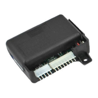
AL-100-H
Control
Module
Page - 14
123456789012
123456789012
123456789012
123456789012
123456789012
123456789012
123456789012
123456789012
123456789012
123456789012
123456789012
123456789012
123456789012
To Ground
Dome
Light
To Constant
12 Volt
Typical Positive Switching
Dome Light System
This is the correct trigger
wire. Connection of the
Green/Violet wire may
be made at any point.
The Black/Red wire is
connected to +12 Volt.
Passenger
Pin
Switch
Note: The Driver
Pin Switch will often
have an extra wire
that activates the “ignition
key in switch” warning
chime. This is the incor-
rect trigger wire.
The Blue wire is a Negative instant trigger used primarily to detect entry into the hood or trunk
area of a vehicle.
CONNECTION: The included pin switches may be installed to provide this trigger circuit;
or, if there are existing switches (example: a light in the luggage compartment or a "Trunk Ajar"
light in the dash), the Blue wire may be connected directly, provided this is a negative ground
switching circuit. An indication of such a circuit is the wire having no voltage present when the
hood or trunk is open, and up to 12 volts when the hood or trunk is closed. This wire cannot
be used with mercury switch types of hood or trunk lights. If the vehicle is equipped with a
usable trunk or hood circuit, locate the proper wire and splice the Blue wire directly to the
vehicle's wire.
Page - 19
123456789012
123456789012
123456789012
123456789012
123456789012
123456789012
123456789012
123456789012
123456789012
123456789012
123456789012
123456789012
123456789012
123456789012
To Ground
Dome
Light
To Constant
12 Volt
Typical Positive Switching
Dome Light System
This is the correct trigger
wire. Connection of the
Green/Violet wire may
be made at any point.
The Black/Red wire is
connected to +12 Volt.
Passenger
Pin
Switch
Note: The Driver
Pin Switch will often
have an extra wire
that activates the “ignition
key in switch” warning
chime. This is the incor-
rect trigger wire.
The Blue wire is a Negative instant trigger used primarily to detect entry into the hood or trunk
area of a vehicle.
CONNECTION: The included pin switches may be installed to provide this trigger circuit;
or, if there are existing switches (example: a light in the luggage compartment or a "Trunk Ajar"
light in the dash), the Blue wire may be connected directly, provided this is a negative ground
switching circuit. An indication of such a circuit is the wire having no voltage present when the
hood or trunk is open, and up to 12 volts when the hood or trunk is closed. This wire cannot
be used with mercury switch types of hood or trunk lights. If the vehicle is equipped with a
usable trunk or hood circuit, locate the proper wire and splice the Blue wire directly to the
vehicle's wire.
Page - 19

 Loading...