ii
Table of Figures
Figure Description Page
1 IEC Symbols ................................................................................. 1-2
2 Limitation of Maximum Setpoint Temperature at Elevated
Ambient Temperatures .............................................................. 2-2
3 Front Panel ................................................................................... 3-1
4 Back Panel .................................................................................... 3-2
5 Overheat Reset Switch ............................................................... 3-3
6 Menu Hierarchy Showing Factory Default Settings .............. 3-3
7 Programming Procedures .......................................................... 3-4
8 Approximate Target Plate Temperature Transition Times
Graph ............................................................................................ 3-4
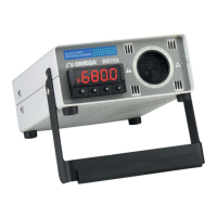
BB703 Blackbody Calibrator
Table of
Figures