COPYRIGHT: OMEGA RESEARCH & DEVELOPMENT 2000
Owner's Guide &
Installation Instructions
K9-MundialK9-Mundial
K9-MundialK9-Mundial
K9-Mundial
Table of Contents
Page 2
Owner’s Guide
Introduction .................................................................................................................. 3
Arming & Disarming the System ...............................................................................4-6
Remote Panic Operation ............................................................................................. 7
The Auxiliary Channel.................................................................................................. 8
LED Status Indicator .............................................................................................11-12
Auxiliary Sensor ....................................................................................................12-13
Programmable Anti-Carjacking Protection ...........................................................13-14
Programmable Features ......................................................................................15- 18
How to Program the Features...............................................................................19-20
How to Program Transmitters to the System ........................................................20-21
Limited Lifetime Warranty ........................................................................... Back Cover
Installation Instructions
Installation .................................................................................................................. 21
Wiring Connections...............................................................................................22-39
Rewired Plug-in Features .....................................................................................40-47
Wiring Diagram Overview .....................................................................................24-25
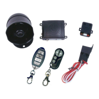
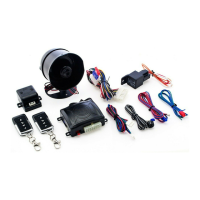
Congratulations on the purchase of your vehicle security system. In learning to
operate your security system, please become familiar with the following three
principal components: the Transmitter, the LED Status Indicator light, and the
Valet/Override Switch.
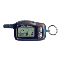
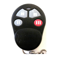
The Transmitter: Each security system comes with two pre-learned transmitters,
but can learn up to 4 different transmitters. Every transmitter has its own unique,
invisible code, which changes with each use. Thus, your transmitter cannot be
duplicated. The transmitter has two buttons: one large button and a smaller button.
Refer to pages 4-8 for detailed transmitter operating instructions.
The Valet/Override Switch: This switch can be used to turn “Off” the alarm portion
of the system, including the programmable Automatic Last Door Arming and
Automatic Rearming features, by placing the system into “Valet Mode”. The Valet/
Override Switch can also be used in conjunction with the vehicle’s ignition key to
perform an “Emergency Override” of the system should the transmitter be lost.
Both of these are explained on pages 8-10.
The LED Indicator Light: The LED Indicates the status of the alarm and serves
as a visual deterrent to break-ins and theft. Refer to pages 11-12.
Introduction
Page 3
Arming & Disarming the System
Upon Arming: • The siren will chirp one time.
• The parking lights will flash once.
• The doors will lock. (If an optional interface is connected)
• The starter interrupt will engage.
• The LED Status Indicator will begin to flash slowly.
THE SIREN WILL CHIRP
ONCE (ARM) OR
TWICE (DISARM)
THE PARKING LIGHTS
WILL FLASH ONCE (ARM)
OR TWICE (DISARM)
THE DOORS WILL LOCK OR UNLOCK
(IF CONNECTED)
The system may be "Armed" by one of two methods. The first method involves the
use of a remote transmitter to "Actively" arm the system, provided the ignition
switch is "off" and the system is not in Valet Mode. The second method is a
programmable feature called “Last Door Arming” in which the alarm will “Passively”
or “self” arm. The system simply reverses its armed/disarmed status when the
transmitter is used. If it is disarmed when the transmitter signal is received, it arms;
if it is armed when the signal is received, it will disarm.
To Actively Arm/Disarm the System:
Press & Release the Large
Transmitter Button.
Page 4