Do you have a question about the Omega WM 09K and is the answer not in the manual?
Instructions for ordering replacement parts, including required information like model number and part name.
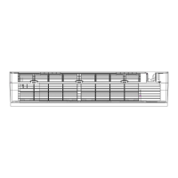
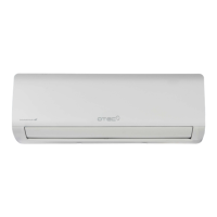
Dimensions for wall split, cassette, and duct type indoor units, including measurements.
Dimensions for OMEGA ODU 18K2 and 27K3 outdoor units, showing measurements D through K.
Explanation of remote controller buttons and basic operation modes, including Cool and Heat Pump setup.
Details on various safety protections like time delay, over/under voltage, and temperature limits.
Explains compressor frequency, fan speed, and operation logic for Cooling, Dry, and Heating modes.
Covers defrosting process, indoor pipe temperature settings, and sleep mode operation.
Details on emergency operation, auto-restart function, and water pump control for specific unit types.
Lists protection types, indoor/outdoor LED codes, and blink times for various faults.
Details the outdoor unit's LED indicator for different failure types and their blink counts.
Wiring schematics for wall split, cassette, and duct type indoor units.
Wiring schematics for outdoor units supporting one to two and one to four indoor units.
Exploded views and parts lists for OMEGA WM 09K, 12K, and 18K wall split indoor units.
Exploded views and parts lists for cassette and duct type indoor units.
Exploded views and parts lists for OMEGA ODU 18K2 and 27K3 outdoor units.
Crucial safety guidelines and recommendations for the proper installation of the air conditioner.
Important safety rules, prohibitions, and recommendations for users regarding operation and maintenance.
Identifies key parts for wall split, cassette, and duct type indoor and outdoor units.
Explains the meaning of various indicators and symbols shown on the unit's display panel.
Specifies pipe sizes, lengths, and cable requirements for air conditioner installation.
Details for installing indoor units (wall, duct, cassette), covering placement and clearances.
Step-by-step instructions for installing the mounting plate for wall split and other types.
Guides on piping, drain pipe slope, indoor unit electrical connections, and refrigerant piping.
Overview of outdoor control system, ODU PCB structure, and component identification.
Provides solutions for various error codes (E1, E2, E6, E3, E7, E8, E0, E5, EA, E9, EU, EE, EC, EP, PA, D3, CL).
Flowcharts for diagnosing IPM/compressor issues and DC over current errors.
Tables showing resistance and voltage characteristics for indoor and outdoor sensors across temperature ranges.
| Brand | Omega |
|---|---|
| Model | WM 09K |
| Category | Air Conditioner |
| Language | English |