Do you have a question about the Omer VEGA 240/50 and is the answer not in the manual?
Lists the parts of the VEGA lift, including platform, ramps, control unit, and hoses.
Lift is designed for indoor/outdoor use, with NEMA 4/4X electrical protection. Suitable for outdoor use under specific conditions.
Lift must be handled by a crane of suitable capacity using nylon wire ropes to avoid paint damage.
The floor must provide a compression strength of at least 0.5 N/mm² (approx. 71 psi).
All electrical connections must be done by professionally qualified staff.
Take care in laying the lift as level as possible, using shims for levelling tolerance of ± 2.5 mm.
Details specifications for anchoring bolts, including type, diameter, depth, and torque.
Provides tightening torques for various components like pins, supports, and anchor bolts.
Minimum concrete thickness is 20 cm for extended surfaces on suitable tamped flooring.
Concrete resistance class Rck=250/300 Kgf/cm², using FeB 44 K reinforcement steel.
Refer to the wiring scheme for connecting electric cables between the lift and the control unit.
The power feeding cable must be 8/4 SO, 90°C, UL-LISTED type.
Ensure the pneumatic system is fed with filtered and lubricated air.
Checkout procedure includes checking platform height, air, motor direction, and latch positions.
Position the vehicle near the torsion bar side. Do not lift vehicles larger or heavier than capacity.
Engages a mechanical lock once height is reached, supporting the load structurally.
Automatically closes to prevent load fall in case of rapid pressure drop or pipe break.
Mobile bars connected to microswitches that stop the lift if lowering movements are obstructed.
Detects level differences between running boards and stops the lift immediately.
Detects entry into hazardous area (0-18"), shuts down lights and photoswitch.
Verify operational performance, clearances, safety latches, and mechanical safety functions.
Check main switch, on/off, emergency stop, lift/lower buttons, and photocell bypass.
Perform load test with platform and weights, check full vertical travel, emergency stop, and safety latches.
Describes buttons: Main Switch (SL), Lift Control (PS), Safety Locks (PC), Lowering (PD), Photocell Override (PEFT).
Lifting is controlled by PS. Lowering (PD) is in two phases: slight raise to release locks, then descent.
Photocell checks platform synchronism; PEFT button overrides it, but mechanical locks are not re-engaged.
Ensure lift is free of grease, oil, objects, cables, or debris before loading a vehicle.
Do not exceed lift capacity. Position vehicle as per manufacturer's distribution table. Ensure vehicle stability.
Do not lift people. Do not tamper with speeds. Do not lift unbalanced loads or use with faulty locks.
Pushing PS energizes C1, starts motor M1, drives oil to cylinders, raising platforms.
Pushing PC energizes EV1, oil drains, platforms lower slightly to engage mechanical locks.
PD energizes C1, T1, EV2. Motor raises slightly to release locks, then EV1 drains oil for descent.
Pressing bars de-energizes R1, locking PD/PC operations; only PS remains active.
Low-voltage 24V AC system with 4-6 neon lamps, protected by IP67 enclosure.
Air-hydraulic jack fed by filtered, lubricated air. Do not exceed lift capacity.
One jacking beam: 70% of lift's rated load. Two jacking beams: 50% each.
Lower lift, remove stop screws, insert beams on guides, reassemble screws before connecting power.
For use in case of power failure. Must be performed by authorized personnel.
Involves inserting lever, pumping, opening manual valve on EV2, and loosening nut on EV1.
Return EV2 manual command, tighten EV1 pin, and replace EV1 cap.
Perform periodic inspections by trained personnel in safe conditions with lift locked.
Recommended periodic maintenance includes lubrication, controls checks, and oil changes.
Lubricate supports/joints, keep lock pins clean. Check cylinder seals and safety devices for leaks/failures.
Change hydraulic unit oil every 100 working hours with the lift lowered.
Operations not listed, like mechanical/hydraulic part replacement, must be done by specialized service personnel.
All worn mechanical, hydraulic, and electrical components must be replaced with original spare parts.
Monthly tasks include lubrication of pins/supports and runway photocell cleaning.
Quarterly tasks include hydraulic unit oil check, base anchoring check, and cylinder lock nut check.
Check main switch, air pressure, fuses, and microswitches if the lift shows no signs of operation.
Verify power supply, fuses, contactor C1 activation, and thermal-cut-out status.
Check motor rotation, oil leaks, pressure, pressure-control valve, and pump coupling.
Check electrovalves EV1/EV2 excitation and flow-regulating valve function.
Check safety valve function and pump wear condition; call service if needed.
Check for oil leaks, base levelling, and torsion bar damage.
Check air pressure, pressure switch calibration, EV2 electrovalve, and cylinder seal wear.
Lists labels for control panel, risks (shock, explosion, fire), fuses, operation, and instructions.
Details labels for electrical shock, explosion risk, fire risk, fuse use, and operation warnings.
Shows labels for T7/2 attachment, air attachment, and general attachment identification.
Details rolling jacks allowed and load limits for VEGA 120, 180, 240, 340, and 450 models.
MAXIMUM LIFT CAPACITY IS 50000 LB. DO NOT OVERLOAD. Identifies O.M.E.R. S.p.A. and CE marking.
Shows ALI, ETL LISTED, and safety standard conformity to ANSI/UL STD 201 and CAN/CSA STD C22.2 NO.68.
Pictograms show: clear area if falling, keep clear of pinch points, chock wheels, read manuals.
Specifies OPERATING TIME: 45 SECONDS and DUTY CYCLE TIME: 10 MINUTES.
Diagram of the internal electric box showing components and their item numbers.
Table listing labels, descriptions, codes, and their respective positions on the panel.
Identifies labels for jacking beam: prohibition of use during movement, air attachment, and load capacity.
Lists descriptions for electrical attachment, T7/2 load capacity, load distribution, serial number, and ETL/ALI plates.
Schematic showing pneumatic components: rapid connection, electrovalve EV2, cylinders, and pressure switch.
Hydraulic power pack schematic with components: oil tank, filters, pumps, valves, and cylinders.
Lists components like oil tank, filters, pumps, valves, hoses, and cylinders with reference numbers.
Shows wiring from control console to lift, including solenoid valves, microswitches, and photoswitches.
Lists components like switches, contactors, fuses, motors, and valves with identification data and notes.
Details microswitches for safety bars/locks, torsion bar, and relays for safety functions.
Diagram showing placement of microswitches (safety locks, bars, height limit), photocell, and lamps.
This section is intended to list all available spare parts for the lift.
Diagram and list of parts for the base structure, including pins, washers, bar covers, and ramps.
Diagram and list of parts for the articulated arms, including pins, nuts, microswitches, and torsion bar group.
Diagram and list of parts for the OF base structure, including pins, washers, bar covers, and ramps.
Diagram and list of parts for the OF articulated arms, including pins, nuts, microswitches, and torsion bar group.
Diagram and list of parts for the runways, including stop bars, pins, photocells, and junction boxes.
Diagram and list of parts for the safety bars, including clamps, levers, microswitches, and screws.
Diagram and list of parts for mechanical safety locks, including pins, nuts, bushes, and microswitches.
Diagram and list of parts for the lifting cylinder, including rod, seals, piston, and cylinder complete.
Diagram and list of parts for the pneumatic cylinder, including nuts, seals, piston rod, and cylinder complete.
Lists all hydraulic and pneumatic system components with descriptions and part numbers.
Diagram and list of parts for the control unit casing, cover, oil tank, nuts, and screws.
Diagram and list of parts for the hydraulic pump group, including motor, coupling, pump, filters, and pipes.
Lists fittings, valves, pressure gauges, and hand pumps for the hydraulic group.
Diagram showing buttons and switches: photocell override, safety locks, lift/lower, lights, and main switch.
Diagram showing components like main switch, contactor, transformer, fuses, relays, and terminal blocks.
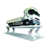
| Brand | Omer |
|---|---|
| Model | VEGA 240/50 |
| Category | Lifting Systems |
| Language | English |