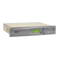
RS-232 Connection (DB-25F)
This connector serves two important purposes: It can be used for a local, bi-directional computer connection
with Omnia-3 Remote Control, or it can be used for troubleshooting and error code resolution. In the former
case, Omnia-3 Remote Control software is utilized. In the latter, any terminal emulation program can be used.
In either case, you must use a standard, straight-through serial cable (not a null modem cable) between the RS-
232 connector and the serial port connector on the computer. Typically, a DB25 male to DB-9 or DB-25 female
cable will be used, with the DB-25 male end of the cable attached to the Omnia-3.
The Remote Control application is available as a free download from the
www.omniaaudio.com website and is
covered in detail in Chapter 8.
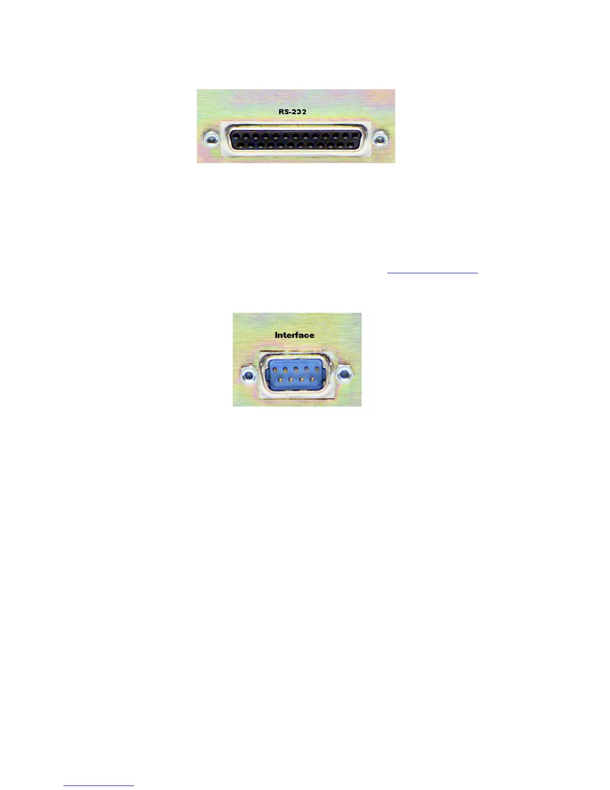
Interface Connection (DB-9M)
The 9-pin male Interface connector uses eight pins as “trigger” inputs with the ninth pin as the ground
reference. The trigger inputs can be used to dynamically alter the Omnia-3’s operational attributes in response
to logic signal transitions. The Omnia-3 responds uniquely on each trigger input to both go-high and go-low
transitions. With eight inputs, and two possible triggers (logic go-high and go-low), sixteen unique “trigger
scripts” can be written (using the Omnia-3 Remote software) to control the Omnia-3 in response to these trigger
input logic transitions. The Trigger Script Interface Editor is covered in detail in Chapter 8.
The Pinout of the Omnia-3 rear-panel DB-9 Interface connector is as follows:
PIN 1 activates Trigger Script 1 PIN 6 activates Trigger Script 2
PIN 2 activates Trigger Script 3 PIN 7 activates Trigger Script 4
PIN 3 activates Trigger Script 8 PIN 8 activates Trigger Script 7
PIN 4 activates Trigger Script 6 PIN 9 activates Trigger Script 5
PIN 5 is connected to ground
Ethernet Connection (Optional)
The Remote Control link for your Omnia-3 over 10BaseT and 100BaseT networks can be utilized if the
Ethernet Interface hardware option is installed. (Part # 2091-00013) Installation instructions are provided with
the hardware. The setup and operation of the Remote Control software application is covered in detail in
Chapters 8 and 9.
16
 Loading...