Do you have a question about the Omnimount OC40FM and is the answer not in the manual?
Contact information for assistance and support.
Important warnings and precautions for wall mount installations.
Hardware components for attaching flat panel displays.
Hardware components for mounting the unit to the wall.
Hardware components specific to the mount product.
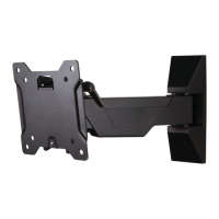
Attaching the monitor using specific hardware for 100x100mm VESA patterns.
Installing adapters for VESA patterns larger than 100x100mm.
Information on obtaining warranty service for customers outside the US.
| Mounting type | Wall |
|---|---|
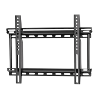
| Maximum VESA mount | 200 x 200 mm |
| Minimum VESA mount | 75 x 75 mm |
| Maximum screen size | 37 \ |
| Minimum screen size | 13 \ |
| Maximum weight capacity | 18.1 kg |
| Pan range | 0 - 180 ° |
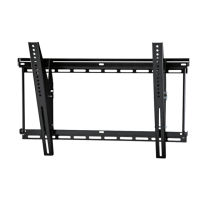
| Tilt angle range | -5 - 15 ° |
| Distance to the wall (min) | 240 mm |
| Certification | UL |
| Product color | Black |
| Manual | Yes |
| Depth | 82 mm |
|---|---|
| Width | 251 mm |
| Height | 155 mm |