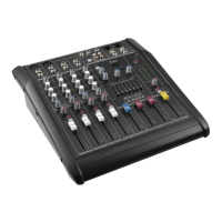
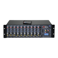
20 dB less gain than the MIC input and does not have phantom power
available. You can use either the MIC input or the line input of a channel,
but not both at the same time.
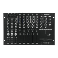
3 INSERT jack
Insert points enable the processing of a signal with dynamic processors or
equalizers. They are sourced post-fader, pre-EQ and pre-aux send.
4 LINE L/R input
Each stereo channel has two balanced line level inputs on 6.3 mm jacks
for left and right channels. If only the left jack (marked "L") is used, the
channel operates in mono.
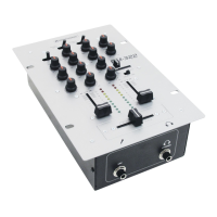
5 GAIN control
Use the gain control to adjust the input gain for the microphone and line
inputs. The scale in the mono input channels has two value ranges: +10 to
+60 dB refers to the MIC input and shows the amplification for the signals
fed in there. +10 to -40 dBu refers to the line input and shows its
sensitivity. The control range for the stereo input channels is +20 to -20 dBu.
6 CLIP LED
This LED serves as overload indication. If it lights up permanently, reduce
the input amplification (turn back the gain control and/or turn back the tone
controls).
7 2-band equalizer All input channels have a 2-band equalizer which provides boost or cut of
up to 15 dB. In the central position, the equalizer is off (flat). The upper
(HIGH) and the lower (LOW) bands are shelving filters that increase or
decrease all frequencies above or below their cut-off frequency. The cut-
off frequencies of the upper and lower bands are 12 kHz and 80 Hz
respectively.
8 Channel fader The channel fader determines the channel's volume in the main mix. The
optimum setting is the 0 (unity gain) position.
9 MON control This control adjusts the level of the channel signal sent to the MON output.
The signal is taken after the channel level control but after the channel EQ.
10 FX control This control adjusts the level of the channel signal sent to the FX output
for effects processing. The signal is taken after the channel level control.
11 PAN/BAL control The panorama control in the mono channel places the mono signal in the
stereo sound. The signal level remains constant. On stereo channels, the
balance control adjusts the balance left/right for the stereo signal.
12 Routing buttons
These buttons select the input signals for channel 9/10 or 11/12.
[9/10 / USB]: button released = signal of the line input 9/10 (4), button
depressed = signal of the USB port).
[11/12 / MP3]: button released = signal of the line input 11/12 (4), button
depressed = signal of the MP3 player).
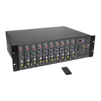
13 Digital effects
processor
This built-in effects module produces high-grade standard effects such as
reverb, chorus, flanger, delay and various combination effects. Use the
PROGRAM control to select an effect preset. The effect selected is
indicated in the display.
14 POWER LED The power indicator lights up when the unit is turned on.
15 +48 V LED Lights up with activated phantom power.
16 Level indication Dual 4-segment LED arrays are provided to monitor the level of the main
left/right output.
17 FX control This control adjusts the level of the built-in effects module sent to the
master channel.
18 +48V button The PHANTOM switch activates the phantom power (necessary to
operate condenser microphones) on the XLR sockets of the mono
channels. The red +48 V LED illuminates when phantom power is on. As a
rule, microphones with unbalanced output cannot be used with phantom
power as they may be damaged.
 Loading...