•
No. Element Function
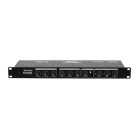
1 EXT FX OUT/IN connectors The FX OUT jack routes the post-fader signal of the individual
channels to an external effects processor. The FX IN jack accepts
the effects mix return. Both jacks are on unbalanced 6.3 mm jacks.
Alternatively, the FX OUT socket can be used to connect another
amplifier, e.g. for the PA application in a secondary room.
2 Balanced MASTER output Balanced stereo XLR output carrying the master output signal
controlled by the main output level control (30); for connecting a
power amplifier.
Note: Always use the balanced master output for cables runs
greater than 5 meters.
3 Unbalanced MASTER output Unbalanced RCA output carrying the same signal as output (2).
4 Balanced BOOTH output Balanced stereo XLR output carrying the booth output signal
controlled by the booth output level control (31); for connecting a
further amplifier e.g. for the monitoring system.
5 Unbalanced BOOTH output Unbalanced RCA output carrying the same signal as output (4).
6 Record output Unbalanced stereo RCA output carrying the master bus signal
independent of the master level control (30).
7 Effect path Send/Return
connectors
With these connections it is possible to route the master signal out
of the mixing console, loop it through an external effects device and
return it to the mixing console. Connect the input of the effects
device to the SEND sockets and the output to the RETURN
sockets. Use the switch (37) to send the effect signal to the master
bus.
Note: If these connections are not used, utilize the jumper cable to
prevent signal dropouts in case of accidental operation of the
switch (37) for the effect path.
8 LINE 1 to 7 / PHONO 1 to 4
inputs
Stereo inputs (RCA) for channel 1-4 for connecting units with line
level outputs such as CD players or turntables with magnetic
system. Set the line/phono switch (9) according to the source used.
The front input selector switches (18) must be set to the left to
select these inputs.
Note: The short-circuit plugs on the phono inputs prevent noise
from getting inside unused inputs. The plugs must not be
connected to the outputs, otherwise there will be a short circuit and
there is no output signal.
9 Line/phono switch Input source selector switch for channel 1-4: button pressed = line
level, button released = phono level.
Note: Switch off the unit before changing the position of a switch.
10 TIMECODE outputs Unbalanced stereo RCA outputs for channel 1-4 carrying the signal
of the inputs (8) above; specifically designed for Timecode
applications. Connect the input of the Timecode system here. The
inputs below (11) accept the Timecode return signal.
11 LINE 2 to 6 inputs Unbalanced stereo RCA inputs for channel 1-4; specifically
designed for Timecode applications. Use these inputs to connect
the outputs of the Timecode system. The front input selector
switches (18) must be set to the right to select these inputs.
Alternatively, you may use the inputs for connecting additional line-
level units.
12 MIC 1 and 2 inputs Balanced XLR jack connectors for microphones. Switch on the
microphones with the corresponding input selector switch (45).
Adjust the microphone volume with the VOL control (44) and the
sound with the HIGH/LOW controls (46).
Please note that no phantom power is available for these inputs, so
they can only be used with dynamic microphones.
13 Ground clamping screws Ground clamping screws for turntables.
14 Power switch Turns the unit on and off. The power indicator lights up when the
unit is turned on.
 Loading...