•
15 Power input with fuse holder
Used to plug in the supplied power cable. Only replace the fuse when
the device is disconnected from mains. Only use fuses of the same
rating and power. The correct fuse value is specified on the rear panel.
16
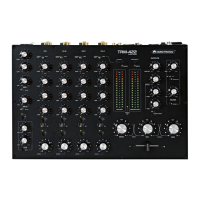
CLIP LED Indicates when the level after the gain control (16) reaches 0 dB, to
allow proper input gain setting depending on the connected audio
source.
17 GAIN control Allows to compensate for different source levels in channels 1-4.
To facilitate proper setting of gain levels, each channel has an
additional CLIP LED (16) which illuminates at 0 dB to give
indication when a suitable gain value is set.
18 Input selector switch Selects one of rear-panel sources to be used with the respective
input channel.
19 HIGH/MID/LOW tone controls
Allows the adjustment of the tonal balance for each of the inputs
separately in three music-specific frequency bands with an
adjustment range of ±10 dB.
20 FILTER assign switches with
LED
When this button is pressed, the channel signal (post-fader) is
routed through the filter section (LED lights up).
21 Crossfader assignment
switch
Allows to send the respective channel’s signal either directly to the
master bus, or to the left side of the crossfader (39) when set to
position “A”, or to the right side of the crossfader when set to the
position “B”. When all input channels are assigned directly to the
master bus, the crossfader is disabled and the desired volume ratio
can be set with the channel controls.
22 CUE assign switch with LED Assigns the respective channel to the headphone bus for pre-fader-
listening (PFL) by means of the headphone output (47). The LED
indicates the pressed position.
23 Channel controls To set the volume for each stereo input channel 1-4.
24 Stereo VU meter
CUE LEVEL
Displays the output level of the monitor (PFL) signal at the
headphone output (47) within the range of -32 dB to +13 dB.
25 AUX input for channel 4 3.5 mm jack input for connecting additional audio sources like
smartphones or portable MP3 players etc. To activate this input,
press the adjacent on/off switch (26) and set the input selector
switch (18) of channel 4 accordingly.
26 On/off switch with LED When the button is pressed, the AUX signal is switched to channel
4 (LED lights up). The input selector switch (18) in channel 4 must
be set to the right to select the AUX input.
27 Power indicator
Lights up when the unit is turned on.
28 VU meter assign switch Selects either the master or booth signal to be displayed on the
main level meter (29).
29 Stereo VU meter
MASTER LEVEL
Displays the output level (within the range of -32 dB to +13 dB) of
either the master or booth signal, depending on the setting of the
display selector switch (28).
30 MASTER volume control This control sets the signal level at the master outputs (2 and 3).
Note: Prior to switching on, turn the master control to minimum to
avoid a possible switching-on noise.
31 BOOTH volume control Sets the signal level at the booth outputs (4 and 5).
32 HIGH/LOW tone controls Allows the adjustment of the high and low range for the booth
outputs with an adjustment range of ±10 dB.
33 RES control Adjusts the resonance or intensity of the filter. The more the control
is turned up, the more the frequencies around the cutoff range are
amplified and a change of timbre is created that makes the audio
signal seem synthetic. The sound varies according to the filter type
selected. To avoid unexpected results it is best to start
experimenting with the control set to a low position.
 Loading...