24
In 3G3MX2-V1, (Register address)=(Register number)-1 。
00: Default
02: Stop
03: Run
04: Free-run stop (FRS)
05: Jogging
06: DC injection braking
07: Retry
08: Trip
09: Undervoltage
0: Initial status
2: Stop
3: Run
4: Free-run stop
5: Jogging
6: DC injection
braking
8: Trip
9: During UV
PID feedback
(Enable when A076 = 02)
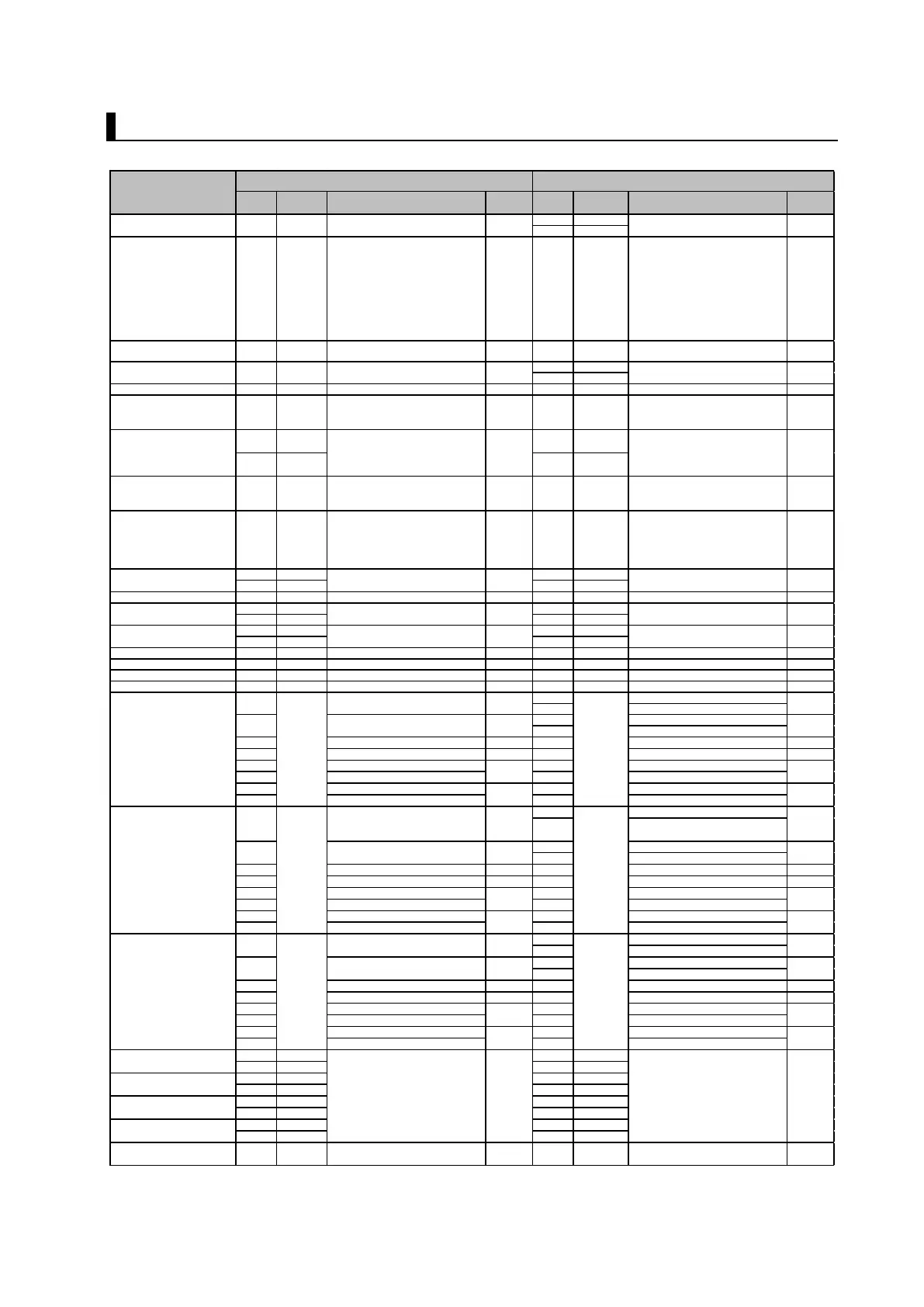
0005h - 0 ~ 1000 0.1[%] 0006h - 0~10000 0.01[%]
Output current monitor 1003h d002 0 ~ 2000 0.1[%] 1003h d002 0~65530 0.01[A]
Rotation direction monitor 1004h d003
00: Stop
01: Forward
02: Reverse
- 1004h d003
0: Stop
1: Forward
2: Reverse
-
1005h d004(MSB) 1005h d004(HIGH)
1006h d004(LSB) 1006h d004(LOW)
Multi-function input monitor 1007h d005
0 to 63
Multi-function input status, Bit 0 =
[1] to Bit 4 = [5]
- 1007h d005
2
0
︓Terminal S1
~2
6
︓Terminal S7/EB
ビット
Multi-function output
monitor
1008h d006
0 to 7
Multi-function output status,
Bit 0 = [P1]
Bit 1 = Not used.
Bit 2 = [MA]
2
0
︓Terminal P1
~2
1
︓Terminal P2
2
6
︓Relay output terminal MA
1009h d007(MSB) 1009h d007(HIGH)
100Ah d007(LSB) 100Ah d007(LOW)
Output voltage monitor 100Ch d013 0 ~ 20000 0.01[%] 1011h d013 0~6000
0.1[V]
100Eh d016(MSB) 1015h d016(HIGH)
100Fh d016(LSB) 1016h d016(LOW)
1010h d017(MSB)
1017h d017(HIGH)
1011h d017(LSB)
1018h d017(LOW)
Fin temperature monitor 116Ah d018 0 ~ 2000 0.1[ ℃ ]
1019h d018 -200~+1500
0.1[°C]
Fault frequency monitor 0011h d080 0 ~ 65535 -
0011h d080 0~65535 1[回]
DC voltage monitor 116Ch d102 0 ~ 9999 0.1[V]
1026h d102 0~10000 0.1[V]
Electronic thermal monitor 116Dh d104 0 ~ 1000 0.1[%]
1028h d104 0~1000
0.1[%]
0016h Trip monitor 1: Current 0.1[A] 0016h Output Current 0.01[A]
0017h Trip monitor 1: Voltage 1[V] 0017h DC Voltage 0.1[V]
0018h Trip monitor 1: Run time (MSB) 0018h Total RUN Time (HIGH)
0019h Trip monitor 1: Run time (LSB) 0019h Total RUN Time (LOW)
001Ah Trip monitor 1: ON time (MSB) 001Ah Total Power ON Time (HIGH)
001Bh Trip monitor 1: ON time (LSB) 001Bh Total Power ON Time (LOW)
Fault Monitor 1 Inverter
Status
0020h Trip monitor 2: Current 0.1[A] 0020h Output Current 0.01[A]
0021h Trip monitor 2: Voltage 1[V] 0021h DC Voltage 0.1[V]
0022h Trip monitor 2: Run time (MSB) 0022h Total RUN Time (HIGH)
0023h Trip monitor 2: Run time (LSB) 0023h Total RUN Time (LOW)
0024h Trip monitor 2: ON time (MSB) 0024h Total Power ON Time (HIGH)
0025h Trip monitor 2: ON time (LSB) 0025h Total Power ON Time (LOW)
002Ah Trip monitor 3: Current 0.1[A] 002Ah Output Current 0.01[A]
002Bh Trip monitor 3: Voltage 1[V] 002Bh DC Voltage 0.1[V]
002Ch Trip monitor 3: Run time (MSB) 002Ch Total RUN Time (HIGH)
002Dh Trip monitor 3: Run time (LSB) 002Dh Total RUN Time (LOW)
002Eh Trip monitor 3: ON time (MSB) 002Eh Total Power ON Time (HIGH)
002Fh Trip monitor 3: ON time (LSB) 002Fh Total Power ON Time (LOW)
1014h F002(MSB) 1103h F002(HIGH)
1015h F002(LSB) 1104h F002(LOW)
1501h F202(MSB) 2103h F202(HIGH)
1502h F202(LSB) 2104h F202(LOW)
1016h F003(MSB) 1105h F003(HIGH)
1017h F003(LSB) 1106h F003(LOW)
1503h F203(MSB) 2105h F203(HIGH)
1504h F203(LSB) 2106h F203(LOW)
Operator rotation direction
selection
1018h F004
0: Forward
1: Reverse
- 1107h F004
00: Forward
01: Reverse
-
1 to 300000
The second decimal place is ignored
when the value is over 10000 (100.0
seconds).
Trip monitor 3: Factor code
Trip monitor 3: Frequency
Trip monitor 2: Frequency
Trip monitor 2: Factor code
Trip monitor 1: Factor code
Trip monitor 1: Frequency
Output frequency monitor
(after conversion)
0~3999600 (In the high-frequency
mode︓~5799420)
PID feedback value monitor
(A075 PID scale)
0~40000 (In the high-frequency
mode︓~58000)
Frequency reference
(Enable when A001 = 03)
 Loading...
