17
4.
Arrangement and Function of Terminal Block
There are some difference of Arrangement and Function of Terminal Block between 3G3JX and
3G3MX2-V1. Before setting, to refer this section. Refer to related product user’s manual.
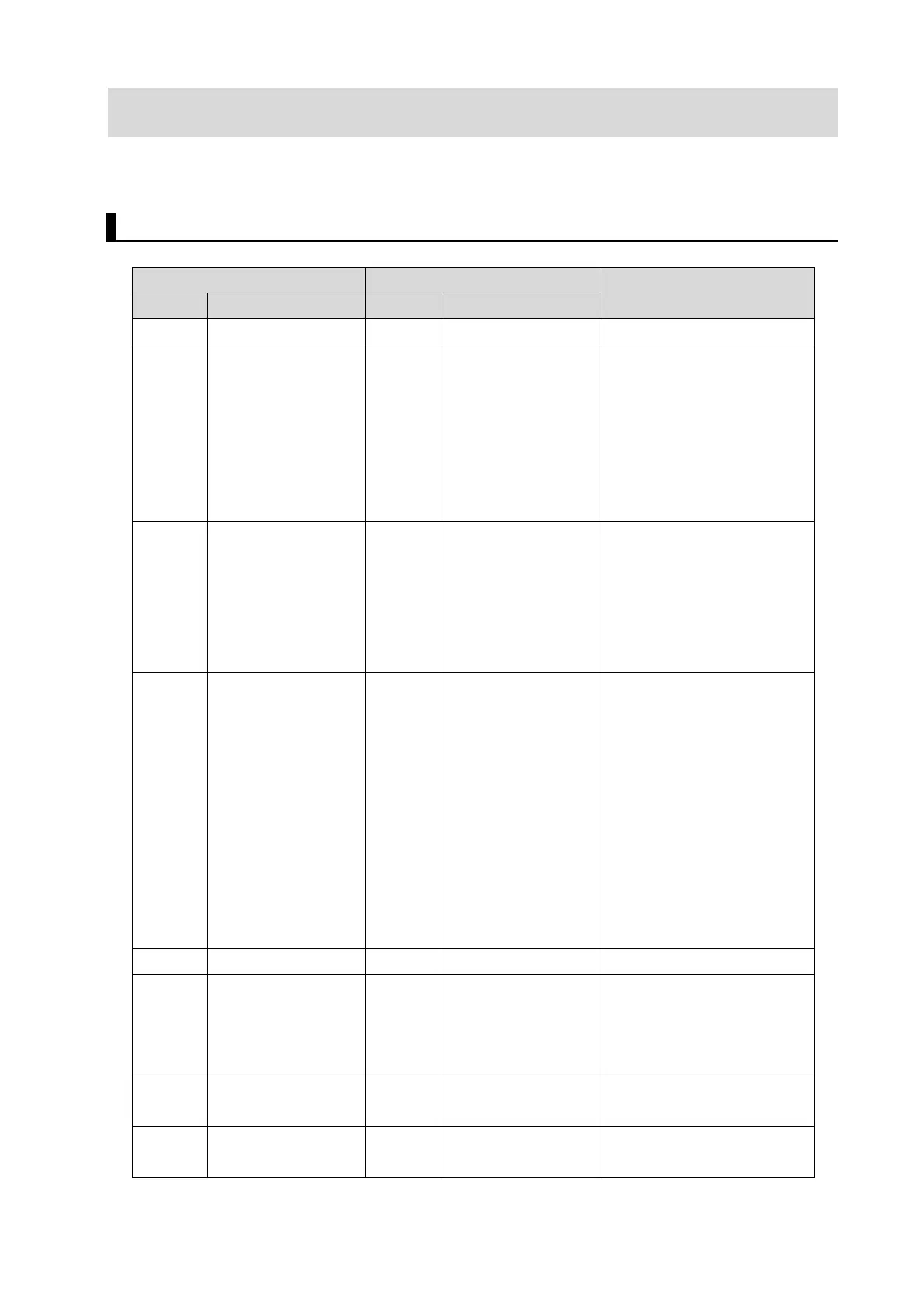
Control Circuit Terminal Block
P24 Internal 24 VDC P24 Internal 24 VDC
PSC Input terminal power
supply
PSC Input terminal power
supply
For sink logic input:
Short-circuited to P24
For source logic input:
Short-circuited to SC. To
activate contact input via an
external power supply,
remove the short-circuit bar.
S1
S2
S3
S4
Multi-function input
S1
S2
S3
S4
Multi-function input The terminals S3 and S4 are
shared with the safety input.
When the safety function
selector switch is ON, S3
and S4 are automatically set
to safety input (GS1, GS2).
S5
Multi-function input
S5 (TH) Multi-function input
(External thermistor
input used in
common)
When the Multi-function
Input S5 Selection (C005) is
set to 19 (TH: PTC
thermistor thermal
protection), the inverter will
trip if the external thermistor
detects a temperature error.
(The inverter trips when the
resistance of the thermistor
is approximately 3 kΩ or
higher.)
SC Input signal common SC Input signal common
AM Analog frequency
monitor/Analog
output current
monitor
AM Multi-function
analog output
(Voltage)
This terminal can output the
specified signal as a 0 to
10-VDC voltage signal.
FS Frequency reference
power supply
FS Frequency reference
power supply
FV Voltage frequency
reference signal
FV Voltage frequency
reference signal
Frequency reference input
(Analog voltage input)
 Loading...