Appendix BSpecifications
146
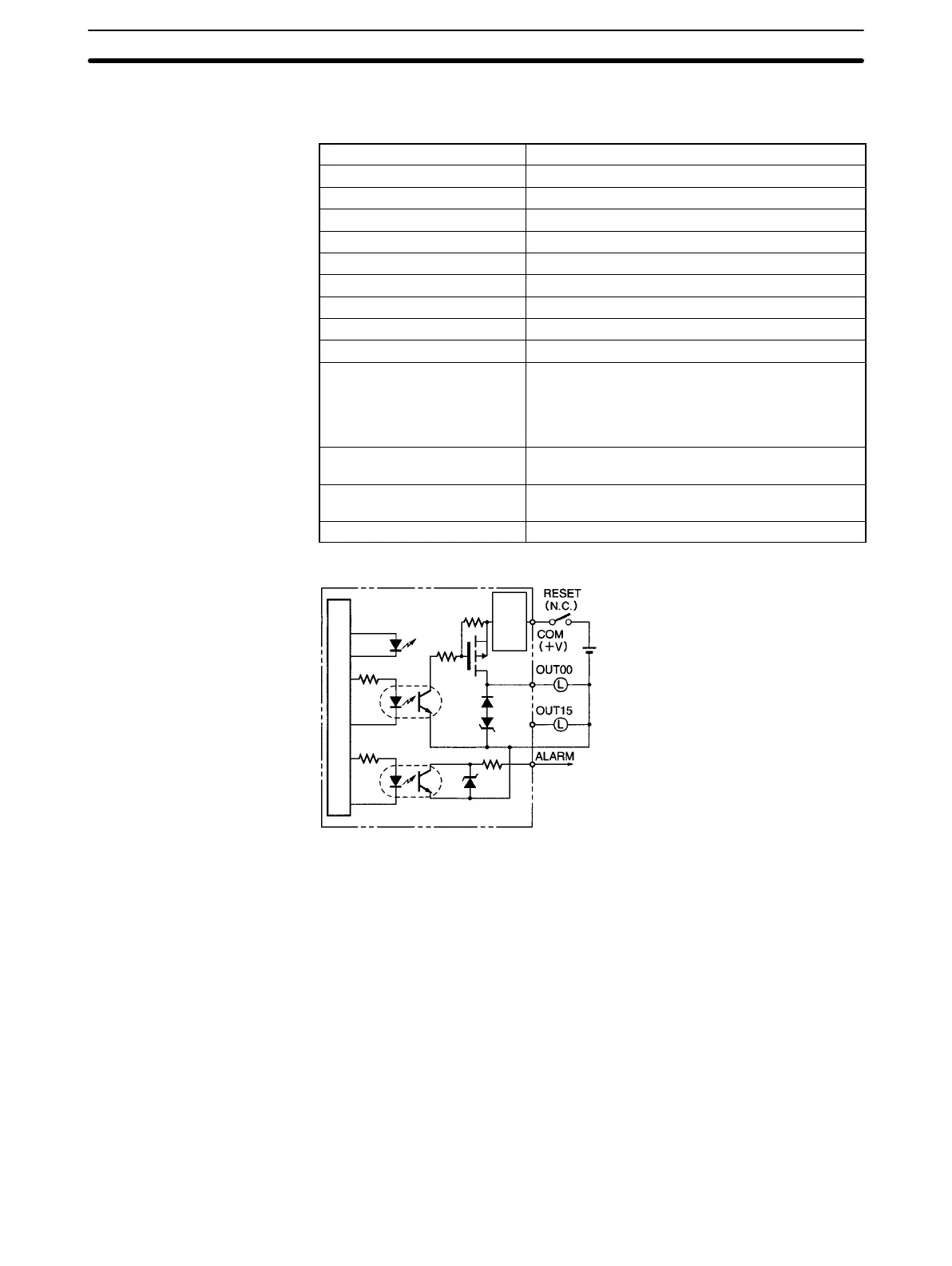
C200H-OD21A Transistor Output Unit (16 Points, Sourcing)
(Load Circuit Protection Provided)
Max. Switching Capacity 24 VDC
+10%
/
–15%
, 1.0 A (4 A/Unit)
Leakage Current 0.1 mA max.
Residual Voltage 0.8 V max.
ON Response Time 0.1 ms max.
OFF Response Time 0.3 ms max.
No. of Circuits 1 (16 points/common)
Internal Current Consumption 160 mA 5 VDC max.
Load Short-circuit Protection Detection current: 1.2 A min (1.6 A typical)
Power for External Supply 35 mA 24 VDC
+10%
/
–15%
min.
Weight 400 g max.
Alarm Output (See note 1.) No. of outputs: 1 (2 kΩ internal resistor)
Connectable Units: Only the following DC Input
Units can be connected:
C200H-ID001, ID211, ID212, IM211 (DC), IM212
(DC), ID215, ID501, MD115, MD215, MD501
Reset Input Used when alarm output turns ON. Value will
depend on the external power supply. (See note 2.)
Load Short-circuit Protection Detection current: 1.2 A min.
(1.6 A typical)
Dimensions B-shape
Circuit Configuration
Internal circuits
Output
indicator
0 V
2 kΩ
to
Short-circuit
protection
circuit
Note When short-circuit/overload protection is activated, all 16 outputs will be switched OFF and the ALARM
output becomes active (low level). The problem can be detected externally by connecting a DC Input Unit to
the ALARM output or by connecting an alarm output indicator. It’s not possible to connect both the Input Unit
and the indicator at the same time. Unless the external I/O power supply is connected and turned ON, the
indicator will not light even if the output contact turns ON.