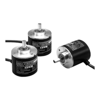
6 E6F-A Absolute 60-mm-dia. Rotary Encoder
Operation and Installation
■ Precautions
• Do not impose voltages exceeding the rated voltage on the E6F-A,
otherwise the E6F-A may be damaged.
• Be sure that the wiring of the E6F-A, including the polarity, is cor-
rect. The E6F-A may be damaged if wired incorrectly.
• Do not short the load of the E6F-A, otherwise the E6F-A may be
damaged.
• Turn OFF the E6F-A while wiring. Wiring while the power supply is
turned ON could result in burning of the output circuit if the output
cable touches the power supply.
• Do not wire power lines or high-tension lines along with the power
supply lines of the E6F-A, otherwise the E6F-A may be damaged
or malfunction.
■ Application
Mounting
Mounting Procedure
1. Insert the shaft into the Coupling.
Do not secure the Coupling and the shaft with screws at this
stage.
2. Secure the E6F-A.
Refer to the following table for the maximum insertion lengths of
the shaft into the Coupling.
3. Secure the Coupling.
4. Connect the power and I/O lines.
Turn OFF the E6F-A when connecting the lines.
5. Turn ON the E6F-A and check the output.
Mounting Information
• Be careful not to allow water, oil, or other substances to be sprayed
on the E6F-A.
• The E6F-A consists of high-precision components. Handle the
E6F-A with utmost care and do not drop it, otherwise malfunction-
ing may result.
• When the E6F-A is to be used in reversing, pay utmost attention to
the mounting direction of the E6F-A, and to the direction of incre-
ment and decrement rotation.
• To match phase Z of the E6F-A to the origin of the device to be
connected to the E6F-A, confirm the phase-Z output when con-
necting the device.
• Do not impose an excessive load on the shaft if the shaft is con-
nected to a gear.
• If the E6F-A is mounted with screws, the tightening torque must not
exceed 0.49 N
¼
m.
• When using a Coupling, mount within the following tolerances.
• If the eccentricity or declination value exceeds the tolerance, an
excessive load imposed on the shaft may damage the E6F-A or
shorten the life of the E6F-A.
Adjustments: Reading Output Codes
• When reading the output code of the E6F-AB3C or E6F-AB3C-C,
read the code only after the LSB (2
0
output) has changed.
Coupling Insertion length
E69-C10B 7.1 mm
E69-C610B
E69-C10M 10.5 mm
Coupling Tightening torque
E69-C10B 0.44 N
¼
m
E69-C610B
E69-C10M 3.5 N
¼
m
Eccentricity tolerance
Declination tolerance
Displacement tolerance in
the shaft direction
0.15 mm max.
2° max.
0.05 mm max.