Er1
Er2
Er3
Er4
Er5
Er6
Er7
OvercurrentatCH1
OvercurrentatCH2
OvercurrentatCH1andCH2
Wrighterrorbyparallelinput
NolightconnectedinCH1
Nolightconnected
Overvoltagefrompowersupply
-Stoplightemission
-ErroroutputON(parallelDO1:ERR)
-Stoplightemission
-ErroroutputON(parallelDO1:ERR)
-Stoplightemission
-ErroroutputON(parallelDO1:ERR)
-Stoplightemission
-ErroroutputON(parallelDO1:ERR)
-Stoplightemission
-ErroroutputON(parallelDO1:ERR)
-Stoplightemission
-ErroroutputON(parallelDO1:ERR)
-Stoplightemission
-ErroroutputON(parallelDO1:ERR)
-Shutdownthecontroller(powersupply)andcheckthelightcondition
andwiring.Thenrestartcontroller.
*Ifeverythingiscorrectbuterrorhappens,theproduct
(lightorcontroller)wouldbedefected.
-InputErrorClear(parallelDI10:CLR)
*Aftererrorclear,tryagainwithcorrecttiming
-Shutdownthecontroller(powersupply)andcheckthelightcondition
andwiring.Thenrestartcontroller.
-Shutdownthecontroller(powersupply)andcheckthelightcondition
andwiring.Thenrestartcontroller.
-Shutdownthecontroller(powersupply)andcheckthelightcondition
andwiring.Thenrestartcontroller.
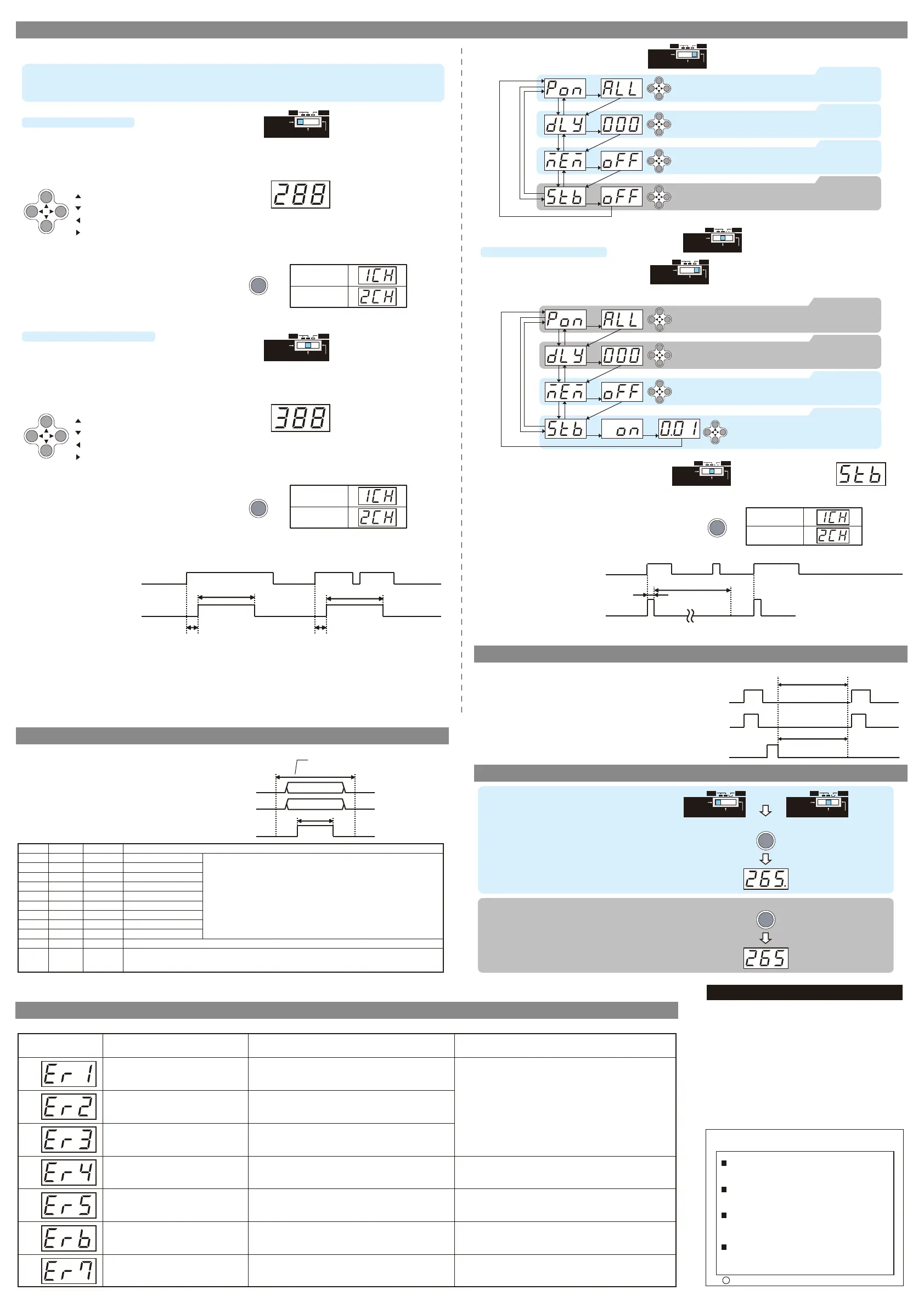
■Mode selection
3 mode for lighting. Use certain one you want.
(1) CONTINUOUS mode (CONT) : continuously lighting
(2) EXTERNAL TRIGGER mode (TRIG) : lighting by trigger input
(3) STROBE mode (STB) : lighting 2 times brighter by trigger input
■ Lighting condition setting for each mode
(1) CONTINUOUS mode(CONT)
- Mode change SW to “CONT”
- Lighting level setting
Set by cross key to change digital value. 400 steps from
1(MIN) -399 to ALL(MAX).
- Lighting level setting
Set by cross key to change digital value. 400 steps from
1(MIN) -399 to ALL(MAX).
- Changing CH
Setting CH changes when CH/ENT key is pushed CH1<>CH2.
After push CH/ENT key, CH number is displayed 1sec.
- Digital value changes by pushing operation key. This value is
synchronized with light intensity in real time. Adjust value
with checking light intensity.
- Digital value changes by pushing operation key. This value is
synchronized with light intensity in real time. Adjust value
with checking light intensity.
7.Setting
11.Error message
10.Key lock function
8.Memory function (MEM)
Attention
- After changing value, when 5 sec have passed with no
operation,the value is saved automatically.
Attention
- After changing value, when 5 sec have passed with no
operation,the value is saved automatically.
Attention
Do not look straigt to lightings when changing mode SW. The lightings flashes when the mode SW is changed CONT ⇒TRIG or SET ⇒TRIG.
Attention
Do not look straigt to lightings when changing mode SW. The lightings flashes when the mode SW is changed CONT ⇒TRIG or SET ⇒TRIG.
Important
Do not input TRIG1/2 during setting by parallel input. Make sure the timing is correct.
Important
With 2CH controller, each CH have to be same mode. If one CH is set to STB mode. The other CH is automatically set to STB mode.
Each signal have to be fixed before and
after “SAVE ON” timing
· Timing chart
1) Change Mode change SW to “SET”
2) Set according to the setting flow
- Emission delay : 0 – 999ms by 1ms (default 0ms) *
- Emission time : 0.1ms – 99.9ms by 0.1ms (default ALL)
ALL : light emitting as long as the trigger is ON
* Emission delay and Emission time can be set in SET mode.
TRIG1/TRIG2
ON
Pluse delay time(Tdelay) Pluse delay time(Tdelay)
Pluse ON time(Tpulse-on)
Pluse ON time(Tpulse-on)
OFF
Light ON
Light OFF
Lighting CH1/CH2
TRIG1/TRIG2
Strobe ON time(ms)
Invalid period of re-trigger input(ms)
ON
OFF
Light ON
Light OFF
Lighting CH1/CH2
・Timing chart
TRIG1/TRIG2
Lighting
CH1/CH2
SAVE
ONLIGHTING OFF
SETTRIG
CONT
(2)EXTERNAL TRIGGER mode (TRIG)
- Mode change SW to “TRIG”
(3)STROBE mode
- Change to STROBE mode by 1) to 3) process
ONLIGHTING OFF
SETTRIG
CONT
ONLIGHTING OFF
SETTRIG
CONT
1) Change Mode change SW to “SET”
2) Set according to the setting flow
ONLIGHTING OFF
SETTRIG
CONT
3) Change Mode change SW to “TRIG”
ONLIGHTING OFF
SETTRIG
CONT
ONLIGHTING OFF
SETTRIG
CONT
ONLIGHTING OFF
SETTRIG
CONT
· Operation key
(UP):Inclease value
(DOWN):Decrease value
(LEFT):Change setting colum to left
(RIGHT):Change setting colum to right
· Operation key
(UP):Inclease value
(DOWN):Decrease value
(LEFT):Change setting colum to left
(RIGHT):Change setting colum to right
CH/ENT
CH/ENT
- Timing chart (TRIG mode)
The light is emitting by external trigger as the chart.
- Strobe time : 0.01 – 5.00ms by 0.01ms
- Invalidation time : Strobe time x 12
The pulse is ignored when the light is emitting.
Keep push 5sec
or
Keep push 5sec
Key lock ON
The dot displayed lower right
- Timing chart (STB mode)
The light is emitting with external trigger as the chart.
■ Key lock function setting
Whole settings are locked by pushing CH/ENT key 5
sec at CONT or TRIG mode
In Key lock condition, only the the Light intensity
value display for each CH can be changed by
CH/ENT key.
■Release Key lock
Push CH/ENT 5 sec
9.Lighting level setting by parallel input
PIN No.
DI1
DI2
DI3
DI4
DI5
DI6
DI7
DI8
DI9
DI11
DI12
Signal
D1
D2
D3
D4
D5
D6
D7
D8
D9
SEL
SAVE
I/O
Input
Input
Input
Input
Input
Input
Input
Input
Input
Input
Input
Fanction
Data 1bit(low)
Data 2bit
Data 3bit
Data 4bit
Data 5bit
Data 6bit
Data 7bit
Data 8bit
Data 9bit(High)
CH select(OFF:CH1,ON:CH2)
Memory function “ON”: The data stored in FLASH memory .
Memory function “OFF” : The data stored in RAM memory .
For more information please refer to “7. Setting ”
1) CONT/TRIG mode
Set Luminance value by D9 – D1, 9bit binary data.
Range 1 – 400 (binary 000000001 – 110010000)
2) STB mode
Set Strobe Lighting time by D9 – D1, 9bit binary data.
Range 0.01 – 5.00ms (1 – 500 binary 000000001 – 111110100)
The following setting is possible by parallel input.
1)
CONT mode and TRIG mode : light intensity value change
2) STB mode : Strobe emission time
Process of parallel input
- Input D1 – D9 binary data
↓
- Select CH by SEL input
↓
- The value will be fixed by SAVE input.
- Changing CH
Setting CH changes when CH/ENT key is pushed CH1<>CH2.
After push CH/ENT key, CH number is displayed 1sec.
- Changing CH
Setting CH changes when CH/ENT key is pushed CH1<>CH2.
After push CH/ENT key, CH number is displayed 1sec.
Display changing
2CH → 1CH
Display changing
1CH → 2CH
CH/ENT
CH/ENT
Display changing
2CH → 1CH
Display changing
1CH → 2CH
Display changing
2CH → 1CH
Display changing
1CH → 2CH
3) Change Mode change SW to “TRIG”,“Stb” is displayed
if succeeded.
ONLIGHTING OFF
SETTRIG
CONT
SAVE
SEL
D1-D9
ON
0.5ms or more
OFF
Key lock OFF
The dot disappeared
CH/ENT
Display Reasonoferror
Errormassagelistandwaytorecover
Behavior Waytorecover
(*)stbisdisplayedatthe
TIRGSW.
▲ Key
▲ Key
▼ Key
▲ Key▼ Key
▼ Key
▲ Key
CH/ENT Key
CH/ENT Key
CH/ENT Key
CH/ENT Key:fix value
CH/ENT Key:fix value
CH/ENT Key:fix value
▼ Key
Pluse ON time setting
Pluse Delay time setting
Memory function setting
Change by cross key. Default value “ALL”
range: · 0.1ms-99.9ms(time)
· ALL(Lightings ON during TRIG1,2 ON)
Change by cross key. Default value “0ms”
range: · 0ms-999ms(time)
Memory Setting for value change by parallel input.
Default value "OFF"
▲ Key
CH/ENT Key
CH/ENT Key:fix value
▼ Key
Confirm STB off
Check if the value is “OFF”. Default value “OFF”
If it is “ON”, change to “OFF”
CH/ENT Key:fix value
CH/ENT Key:fix value
CH/ENT Key:fix value
Change by cross key. Default value “ALL”
range: · 0.1ms-99.9ms(time)
· ALL(Lightings ON during TRIG1,2 ON)
Change by cross key. Default value “0ms”
range: · 0ms-999ms(time)
▲ Key
▲ Key
▼ Key
▼ Key
▼ Key
▲ Key
CH/ENT Key CH/ENT Key
CH/ENT Key
CH/ENT Key
▼ Key
No setting needed
No setting needed
Strobe setting
Change by cross key.
Default value “0.01ms”
range:0.01ms-5.00ms(time)
CH/ENT Key:fix value
▲ Key▼ Key
CH/ENT Key
▲ Key
Memory function setting
Memory Setting for value change by parallel input.
Default value "OFF"
Data saving(2s)
Invalid period of trigger input
ON
OFF
ON
OFF
Light ON
Light OFF
This function applies only when using the external control.
“ON” : The data stored in FLASH(nonvolatile) memory.
Keep data even when the power turned off. 2 sec
required for data saving.
Make interval at least 2 sec between “SAVE” signal
and next “TRIG” signal.
“OFF”: The data stored in RAM(volatile) memory.
Return to the last saving data when the power is
turned off.
Suitability for Use
s
Omron Companies shall not be responsible for conformity with any standards,
codes or regulations which apply to the combination of the Product in the
Buyer’s application or use of the Product. At Buyer’s request, Omron will
provide applicable third party certification documents identifying ratings and
limitations of use which apply to the Product. This information by itself is not
sufficient for a complete determination of the suitability of the Product in
combination with the end product, machine, system, or other application or
use. Buyer shall be solely responsible for determining appropriateness of the
particular Product with respect to Buyer’s application, product or system.
Buyer shall take application responsibility in all cases.
NEVER USE THE PRODUCT FOR AN APPLICATION INVOLVING
SERIOUS RISK TO LIFE OR PROPERTY WITHOUT ENSURING THAT THE
SYSTEM AS A WHOLE HAS BEEN DESIGNED TO ADDRESS THE RISKS,
AND THAT THE OMRON PRODUCT(S) IS PROPERLY RATED AND
INSTALLED FOR THE INTENDED USE WITHIN THE OVERALL
EQUIPMENT OR SYSTEM.
See also Product catalog for Warranty and Limitation of Liability.
Oct, 2014
D
OMRON Corporation
Industrial Automation Company
Contact: www.ia.omron.com
Tokyo, JAPAN
OMRON ELECTRONICS LLC
2895 Greenspoint Parkway, Suite 200
Hoffman Estates, IL 60169 U.S.A.
Tel: (1) 847-843-7900/Fax: (1) 847-843-7787
OMRON ASIA PACIFIC PTE. LTD.
No. 438A Alexandra Road # 05-05/08 (Lobby 2),
Alexandra Technopark,
Singapore 119967
Tel: (65) 6835-3011/Fax: (65) 6835-2711
OMRON (CHINA) CO., LTD.
Room 2211, Bank of China Tower,
200 Yin Cheng Zhong Road,
PuDong New Area, Shanghai, 200120, China
Tel: (86) 21-5037-2222/Fax: (86) 21-5037-2200
OMRON EUROPE B.V.
Sensor Business Unit
Carl-Benz-Str. 4, D-71154 Nufringen, Germany
Tel: (49) 7032-811-0/Fax: (49) 7032-811-199
Regional Headquarters
 Loading...